Front and rear panel controls and indicators 5 – Drake VM2551A Agile Modulator – 550 MHz User Manual
Page 5
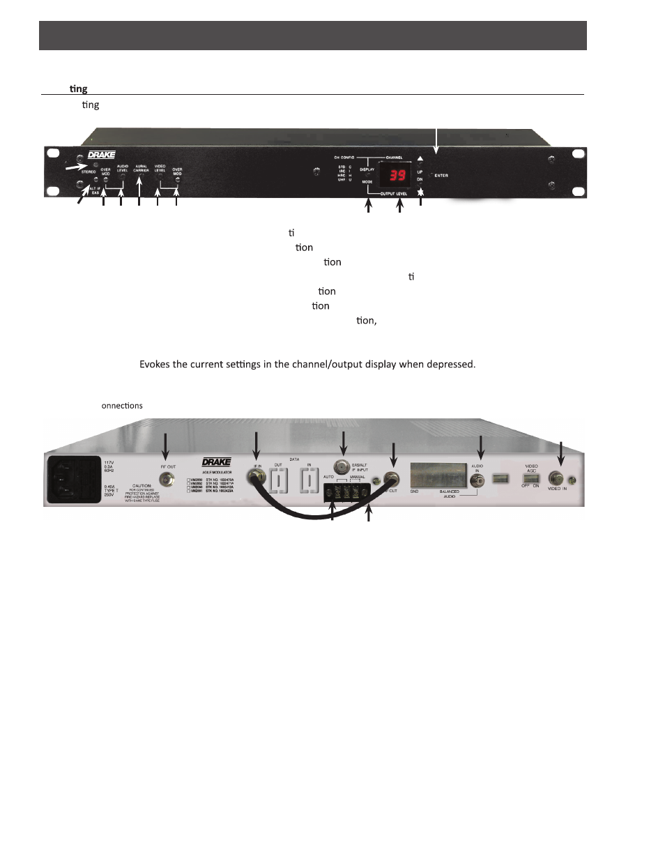
Front and Rear Panel Controls and Indicators 5
VM2551A VIDEO MODULATOR
Opera
Controls
All opera
controls and indicators for the modulator are located on, or are accessible from the front panel.
[1] EAS/ALT INDICATOR: Lights Red when EAS/ALT is ac ve.
[2] VIDEO OVERMODULATION LED: Lights when modula
is above 87.5%.
[3] VIDEO MODULATION LEVEL: Adjusts percentage of modula
.
[4] AURAL-TO-VISUAL CARRIER RATIO: Controls amplitude of aural RF carrier rela ve to visual RF carrier.
[5] AUDIO MODULATION LEVEL: Adjusts aural carrier modula
.
[6] AUDIO OVERMODULATION LED: Lights when peak devia
of aural carrier is over 25 kHz.
[7] DISPLAY MODE BUTTON: Used to scroll through channel configura
output level and modes.
[8] CHANNEL, CHANNEL CONFIGURATION/OUTPUT LEVEL DISPLAY
[9] UP/DOWN BUTTONS:
[10] ENTER BUTTON:
[11] STEREO INDICATOR:
Note: All c
to the unit are made at the rear panel.
Figure 2 - Rear Panel
Figure 1 - Front Panel
[1] RF OUTPUT: + 60 dBmV
[2] IF INPUT: +35 dBmV IF Input
[3] EAS/ALT IF INPUT: Emergency Alert or Alternate IF Input
[4] IF OUT: +35 dBmV IF Output (See note #8 below)
[5] EAS/ALT IF TERMINAL:
[6] AUDIO INPUT: Audio input (standard)
[7] VIDEO INPUT: 1 Volt PP video input
[8] IF LOOP CABLE: The IF loop cable (supplied) must be installed to provide RF continuity. The modulator will
not have an RF output without the IF loop installed.
[1]
[1]
[2]
[3]
[4]
[5]
[6]
[7]
[8]
[11]
[6] [5] [4] [3] [2]
[7]
[8]
[9]
[10]
EAS / ALT
IF mode selection (see page 7)
Not used.
Used to scroll through the channel, channel configuration and output level modes.