Catv channel output frequencies, Catv, Catv +100 – Drake MPM860AG Agile Processor Module User Manual
Page 5: Table 1, Catv channel output frequencies 5 4 installation
5
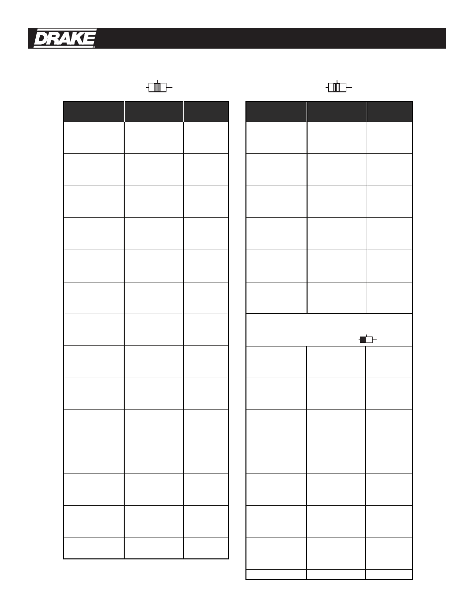
Output Channel Visual Carrier Frequency
Output Channel
Visual Carrier Frequency
Switch Setting Frequency (MHz) Offset (kHz) Switch Setting Frequency (MHz) Offset (kHz)
TABLE 1:
CATV
CATV
+100
CATV
BC
TV
CATV +100
CATV
+100
CATV
BC
TV
CATV
+100
CATV
BC
TV
CONNECTIONS AND CONTROLS
All connections to and from each processor are
made through the rear panel.
INSTALLATION NOTES
Level adjustment provides optimum performance
in multi-channel installations. The output levels
should be checked periodically with a spectrum
analyzer or appropriate meter to insure that
output levels are properly set.
RACK MOUNTING
Adequate ventilation is very important in rack
mounting installations. Excessive heat will
shorten component life and performance.
The RMM12 or RMM4A chassis should be spaced
at least 1RU apart whenever and wherever
possible. Some air movement is a mandatory
requirement in enclosed rack cabinets.
CATV Channel Output Frequencies 5
4 Installation
02
03
04
05
06
07
08
09
10
11
12
13
14
15
16
17
18
19
20
21
22
23
24
25
26
27
28
29
30
31
32
33
34
35
36
37
38
39
40
41
42
43
44
45
46
47
48
49
50
51
52
53
54
55
56
57
58
59
60
61
62
63
64
65
66
67
68
69
55.25
61.25
67.25
77.25
83.25
175.25
181.25
187.25
193.25
199.25
205.25
211.25
121.25
127.25
133.25
139.25
145.25
151.25
157.25
163.25
169.25
217.25
223.25
229.25
235.25
241.25
247.25
253.25
259.25
265.25
271.25
277.25
283.25
289.25
295.25
301.25
307.25
313.25
319.25
325.25
331.25
337.25
343.25
349.25
355.25
361.25
367.25
373.25
379.25
385.25
391.25
397.25
403.25
409.25
415.25
421.25
427.25
433.25
439.25
445.25
451.25
457.25
463.25
469.25
475.25
481.25
487.25
493.25
NONE
NONE
NONE
NONE
NONE
NONE
NONE
NONE
NONE
NONE
NONE
NONE
±12.5
±12.5
±12.5
NONE
NONE
NONE
NONE
NONE
NONE
NONE
+12.5
+12.5
+12.5
+12.5
+12.5
+12.5
+12.5
+12.5
+12.5
+12.5
+12.5
+12.5
+12.5
+12.5
+12.5
+12.5
+12.5
+12.5
+25.0
+12.5
+12.5
+12.5
+12.5
+12.5
+12.5
+12.5
+12.5
+12.5
+12.5
+12.5
NONE
NONE
NONE
NONE
NONE
NONE
NONE
NONE
NONE
NONE
NONE
NONE
NONE
NONE
NONE
NONE
70
71
72
73
74
75
76
77
78
79
80
81
82
83
84
85
86
87
88
89
90
91
92
93
94
95
96
97
98
99
100
101
102
103
104
105
106
107
108
109
110
111
112
113
114
115
116
117
118
119
120
121
122
123
124
125
126
127
128
129
130
131
132
133
134
135
NONE
NONE
NONE
NONE
NONE
NONE
NONE
NONE
NONE
NONE
NONE
NONE
NONE
NONE
NONE
NONE
NONE
NONE
NONE
NONE
NONE
NONE
NONE
NONE
NONE
NONE
NONE
NONE
+25.0
+25.0
NONE
NONE
NONE
NONE
NONE
NONE
NONE
NONE
NONE
NONE
NONE
NONE
NONE
NONE
NONE
NONE
NONE
NONE
NONE
NONE
NONE
NONE
NONE
NONE
NONE
NONE
NONE
NONE
NONE
NONE
NONE
NONE
NONE
NONE
NONE
NONE
499.25
505.25
511.25
517.25
523.25
529.25
535.25
541.25
547.25
553.25
559.25
565.25
571.25
577.25
583.25
589.25
595.25
601.25
607.25
613.25
619.25
625.25
631.25
637.25
643.25
91.25
97.25
103.25
109.25
115.25
649.25
655.25
661.25
667.25
673.25
679.25
685.25
691.25
697.25
703.25
709.25
715.25
721.25
727.25
733.25
739.25
745.25
751.25
757.25
763.25
769.25
775.25
781.25
787.25
793.25
799.25
805.25
811.25
817.25
823.25
829.25
835.25
841.25
847.25
853.25
859.25
POWER SUPPLY REQUIREMENTS
Power for units mounted in the RMM12 rack
mounting chassis is to be supplied by a Drake
model PSM121 Mini Mod Series Power Supply. A
single PSM121 can power up to twelve (12) units
of most Drake Mini Mod Series models.
Likewise, an RMM12 can hold up to twelve (12)
Drake Mini Mod Series models as well as a single
PSM121 Mini Mod Series Power Supply.
The power supply in the four-position Drake model
RMM4A system is built into the chassis and cannot
be removed. The RMM4A will securely hold and
power up to four (4) units of the MPM860AG.
FREQUENCY CHART
The table on the following page shows the
standard CATV channel coverage. Where an offset
is indicated, this amount of positive frequency
offset is added to the frequency indicated in the
middle column. As shown, this occurs only on
channels required to be offset by the FCC.
HRC or IRC frequencies can be set by means of an
internal jumper (see Figure 3).
No jumper will result in the STD channel plan
selection.
CATV Channel Output Frequencies