Installation - applications 3 – Drake AC1686 Active Combiner 860 MHz User Manual
Page 5
Installation - Applications 3
CONNECTIONS AND CONTROLS
All connections, except the output monitor test port, to
and from the AC1686, are made through the rear
panel. A convenient front panel gain adjustment is also
provided. The included application diagrams are
drawn as Block Diagrams to more efficiently illustrate
the system connections.
INSTALLATION NOTES
Level adjustment is critical in a multichannel installation,
and should be checked periodically with a spectrum
analyzer or CATV signal level meter.
Care should be taken to insure that all channels are
within ±1 dB of the desired output for best adjacent
channel operation. In addition, all A/V ratios should be
held to -15 dB or less.
Adequate ventilation is very important in multichannel
installations. Units should be spaced apart by at least
one panel height, and some air movement is advisable
in enclosed rack cabinets. Excessive heat will shorten
component life and equipment performance will be
degraded without proper cooling.
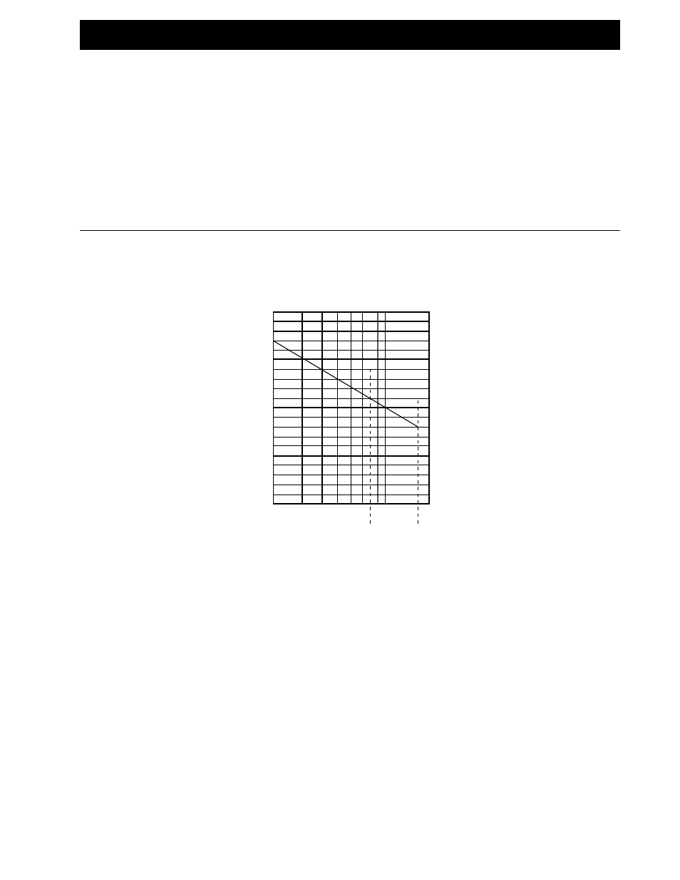
Use the following chart to determine the maximum
permissible output levels for the specific number of
combined input channels from 2 - 16.
NUMBER OF COMBINED
CHANNELS
MAXIMUM
PERMISSIBLE
OUTPUT
LEVELS
(each
channel)
at
RF
OUT
If these levels are exceeded, second and third order
distortion products may exceed acceptable levels.
dBmV
+60
+55
+50
+45
+40
8CH 16CH
2 3 4 5 6 7 8 9 10
Application Notes:
1)
Use with 16 modulators with 45 dBmV output levels.
Set all modulator output levels to +45 dBmV. Adjust
input attenuator on the active combiner until the
combiner output levels are all at the desired output
level, but not exceeding 48 dBmV per channel, as
measured at the combiner output port. Slightly level
each modulator, as required, by adjusting each
modulator output. Do not exceed maximum output
levels shown in the above graph.
2)
Use with 16 modulators with 55 dBmV output levels.
Set all modulator output levels to +55 dBmV. For best
noise performance, it is best to keep modulator outputs
within 5 dB of the maximum output. Start with the active
combiner attenuation adjustment at the extreme
counterclockwise position and adjust to bring output
levels up to desired level. Do not exceed the maximum
shown in the above graph. Next, adjust individual
modulator outputs slightly to equalize all channels.