2 front and rear panel connections and controls – Drake AC1686 Active Combiner 860 MHz User Manual
Page 4
AC1686 ACTIVE COMBINER
POWER
OUTPUT TEST
20 dB
OUTPUT LEVEL
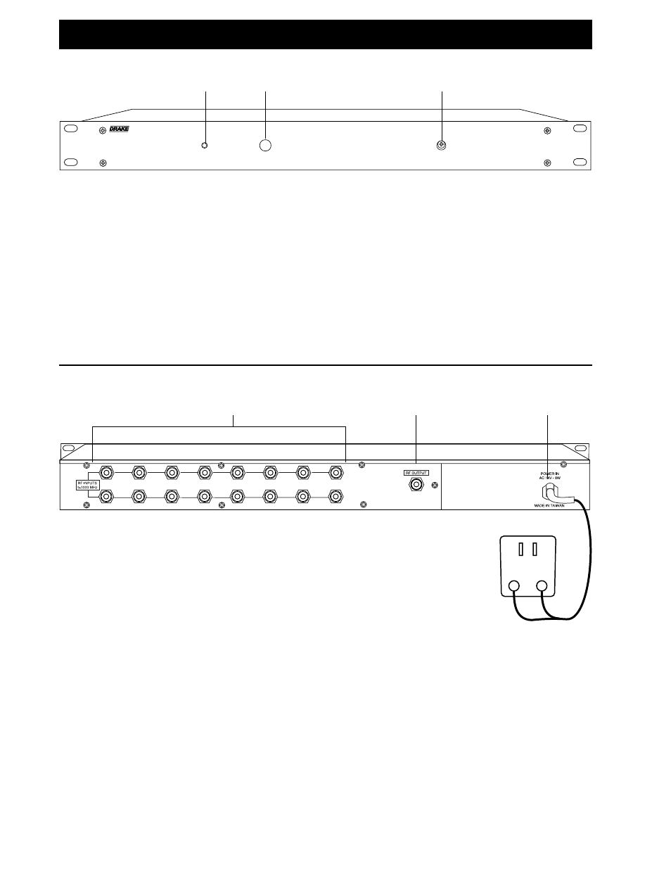
2 Front and Rear Panel Connections and Controls
F1 F2
F3
F3 - OUTPUT LEVEL Control
This screwdriver adjusted attenuator permits setting the
attenuation of the combined signals applied to the
‘INPUTS 1-16’ rear panel connectors prior to
amplification. The range of attenuation adjustment is at
least 15 dB.
F1 - POWER Indicator
Lights to indicate that the combiner is connected to a
source of power.
F2 - MONITOR Test Point Connector
This type F connector is provided for sampling the
combined RF Output of the combiner. The level of each
signal at this connector is approximately 20 dB below
the level of the respective signal present at the rear
panel ‘RF OUTPUT’ connector. The rear panel output
connector must be terminated in 75 Ohms.
R1 - INPUTS 1-16 Connectors
These type F connectors accept signals with levels up
to 60 dBmV each, maximum.
R2 - RF OUT Connector
This type F connector provides the single coax output
connection of the combined signal inputs. With the
front panel ‘OUTPUT LEVELS 1-16’ control set
maximum clockwise, the signal level output is
approximately 2 dB to 3 dB above the respective signal
level input at the ‘INPUTS 1-16’ connectors.
R3 - POWER CABLE
When this cable is connected to the accompanying 120
VAC power adapter, and the adapter is plugged into a
nominal 120 VAC power source, 14 VAC power will be
supplied to the unit.
R1
R2
R3
FRONT PANEL
REAR PANEL