Mounting and connection – Digi-Star EZ 2000/V User Manual
Page 10
Digi-Star Model EZ2000/EZ2000V
3. Mounting and connection
8
3. Mounting and connection
INDICATOR MOUNTING
The indicator is easily attached to the
Indicator Mounting Bracket by hooking the
top over the plate and securing the bottom
with two (2) bolts (size# 10 x 24 x 3/4") and
nuts.
POWER CONNECTION
Warning!
Always disconnect the indicator power cord
before “jump starting” or fast charging a
battery.
Disconnect all indicator leads before
welding on equipment. Failure to do so can
cause surges which will damage the scale.
The power cable should be connected
directly to a vehicle battery or regulated
power supply. The scale end of the power
cable is attached to the J901 connector
located on the bottom panel of the scale.
Connect the RED wire from the power
cable to +12VDC and the BLACK wire to
GROUND. The indicator is fused
internally at 4 amps.
Wire Color
Wire Function
RED
Battery (+12Vdc)
BLACK
GROUND
ORANGE
NA
BLUE
NA
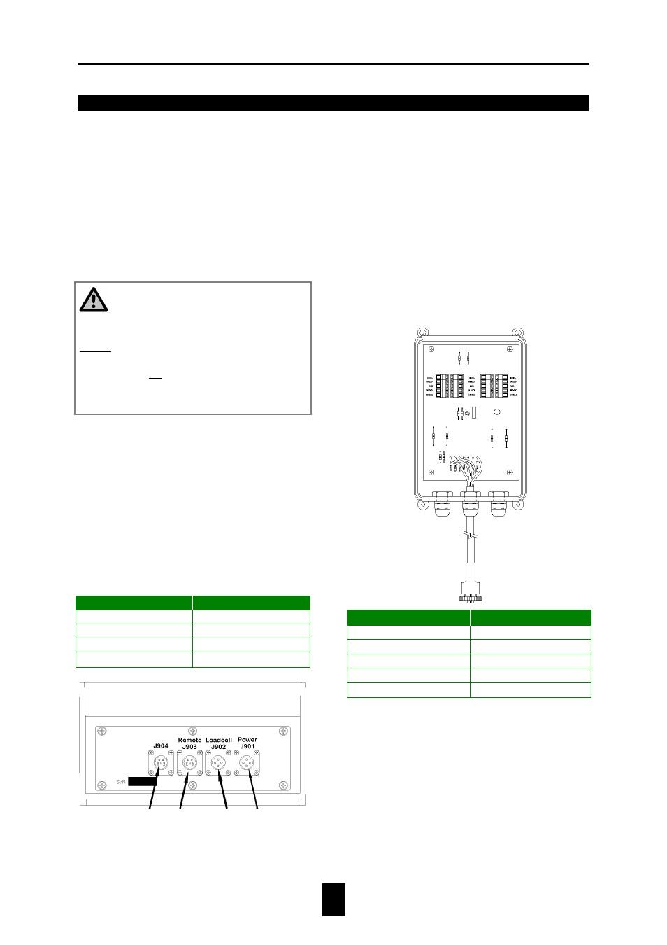
LOAD CELL CONNECTION
The indicator is designed to operate with
strain gage load cells. The system will
normally be supplied with a “J-BOX” cable
going between the indicator and the load cell
junction box. Extension Kits are available
from your dealer in various lengths.
To connect the load cells, attach the junction
box cable to the J902 connector on the
bottom panel of the scale. Connect the load
cell cables to the junction box as shown
below.
!
Follow color key on circuit board to insure
proper connection of load cell wires.
Serial
Port
Cable
(Optional)
Junction
Box
Cable
Remote
Display
Cable
(Optional)
Power
Cable
WHITE
SIGNAL +
GREEN
SIGNAL -
RED
EXCITATION +
BLACK
EXCITATION -
SHIELD
SHIELD
Terminal Color
Description