Power connection, Load cell connection – Digi-Star AGCO - White 8816 User Manual
Page 9
Indicator Mounting
D3879-US – Rev B
AGCO – White – 8800/8500 Series
7
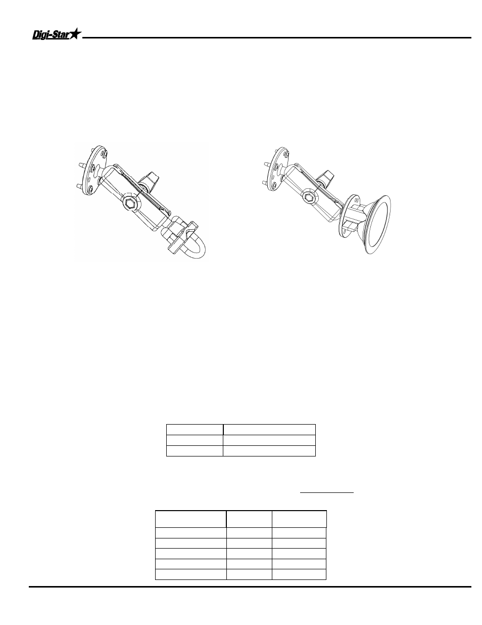
INDICATOR MOUNTING
The scale indicator can be mounted in the tractor cab or on the drill, planter or seeder with swivel mounting
pack (406629). Two cables must be connected to the indicator bottom panel, J-Box and power cables. Refer
to Indicator Manual D3831-US for details of indicator mounting options and connection of power cord.
1. Bolt the readout in the cab, or mount the swivel bracket on the drill, planter or seeder.
2. Install power cord to a 12-volt negative ground battery.
3. Route J-box cable to indicator and install to indicator bottom panel.
4. Program indicator with set-up #115015 and calibration #4072. This is for scale system with 10,000 lbs
capacity load cells.
Power Connection:
The power cable should be connected directly to a vehicle battery or regulated power supply. The scale end of
the power cable is attached to the J901 connector located on the bottom panel of the indicator.
Connect the RED wire from the power cable to +12 VDC and the BLACK wire to GROUND. The indicator is
fused internally at 4 amps.
Power Cable Connections:
Wire color Wire Function
Red
Battery (+12 VDC)
Black
GROUND
Load Cell Connection:
The indicator is designed to operate with strain gage load cells. The indicator will normally be supplied with a
“J-BOX” cable going between the scale and the load cell junction box. Extension kits are available from your
dealer in various lengths.
Load Cell Wire Digi-Star Function
1
RED
+EX
2
GREEN
-SIG
3
WHITE
+SIG
4
BLACK
-EX
5
CLEAR
SHIELD
INDICATOR MOUNTINGS
TRACTOR CAB MOUNTING
U-BOLT RAM MOUNT