Chapter 2 - hardware installation, System board layout, System memory – DFI BT160 User Manual
Page 9: Chapter 2 chapter 2 - hardware installation, Rear i/o onboard i/o storage expansion, Chapter 2 hardware installation, Ddr3l-2 ddr3l-1 standby power led, Intel atom
www.dfi .com
9
Chapter 2 Hardware Installation
Chapter 2
Chapter 2 - Hardware Installation
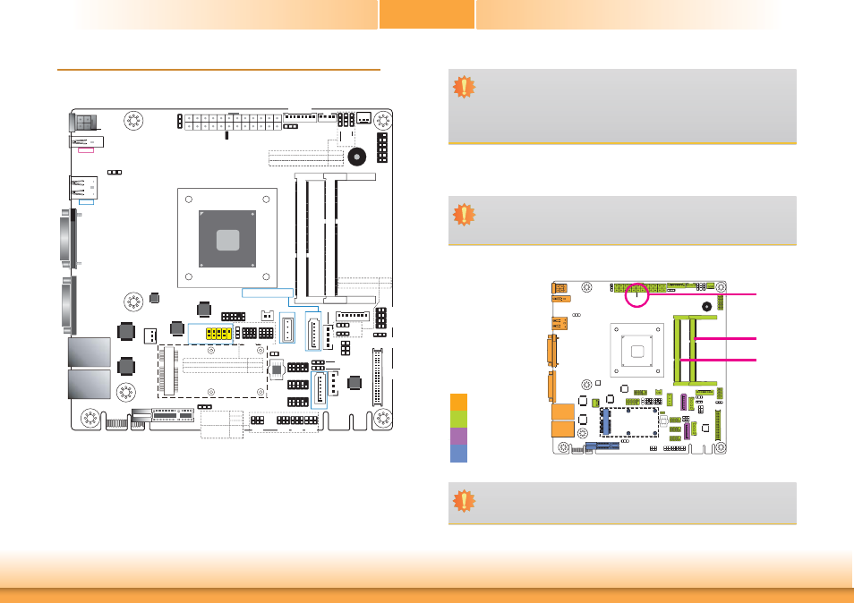
Board Layout
System Memory
Important:
Electrostatic discharge (ESD) can damage your board, processor, disk drives, add-in
boards, and other components. Perform installation procedures at an ESD workstation
only. If such a station is not available, you can provide some ESD protection by wear-
ing an antistatic wrist strap and attaching it to a metal part of the system chassis. If
a wrist strap is unavailable, establish and maintain contact with the system chassis
throughout any procedures requiring ESD protection.
Important:
When the Standby Power LED lights red, it indicates that there is power on the sys-
tem board. Power-off the PC then unplug the power cord prior to installing any de-
vices. Failure to do so will cause severe damage to the motherboard and components.
Rear I/O
Onboard I/O
Storage
Expansion
DDR3L-2
DDR3L-1
Standby
Power LED
COM 1
DC-in
4-pin Power
(optional)
SPI
Flash
BIOS
Mini PCIe
1
2
10
9
1
2
10
9
1
2
10
9
COM 3
COM 4
1 2
Battery
COM 2
DFI Proprietary
Extension Bus
LAN 1
LAN 2
1
USB 1-2 Power
Select (JP5)
8 7
2 1
LAN2 State
LAN2 State
LAN1 State
LAN1 State
1
LCD/Inverter
Power
Mini PCIe/mSATA
Power Select (JP6)
1
Auto Power-on
Select (JP12)
1
1
Digital I/O
Power
(JP17)
(JP20)
(JP18)
1 1 1
Digital I/O Power Select
Digital I/O 0-3 Output State
Digital I/O 4-7 Output State
(JP17)
(JP20)
(JP18)
1
System
Fan
1
2
11
12
Front
Panel
USB 4-5
USB 2.0
9
10
1
2
1
4
SATA
Power 1
1
4
SATA
Power 0
1
Chassis
Intrusion
(JP15)
(JP16)
1
1
Dimming Mode Select
Backlight Power Select
(JP15)
(JP16)
SATA DOM Power
Select (JP13)
USB 3 Power
Select (JP14)
1
1
VGA
USB 2
USB 2.0
USB 1
USB 3.0
12
24
1
13
ATX Power
Standby
Power LED
Clear CMOS
Data (JP8)
Intel Atom
E3800 Series
Buzzer
DDR3L_2 SODIMM
DDR3L_1 SODIMM
2
1
39
40
NXP
PTN3460
1
LCD/Inverter Power
Select (JP21)
SMSC
USB4604
ISL95837
ASMedia
ASM1182
1
12
2
11
LPC
PCIe x1
1
CPU Fan
Digital I/O
1
SATA 0
1
(JP7)
1
12
10
3
1
USB 4-5 Power Select
Mini PCIe/mSATA Signal Select
(JP7)
(JP9)
(JP10)
USB 3
USB 2.0
1
4
SATA 2.0
Note:
SATA0 supports SATA DOM.
SATA 2.0
SATA 1
LVDS LCD
Panel
Panel
Power
Select
(JP19)
1
2
5
6
Intel
WGI210AT
Intel
WGI210AT
1
2
5
6
1
2
5
6
1
2
5
6
1
2
5
6
(JP22) (JP25) (JP23)
(JP24)
COM 4
RS232/422/485
Select
(JP22)
(JP23)
(JP24)
COM 4
RS232/Power
Select
(JP25)
1
12
10
3
1
(JP9) (JP10)
SATA 1/mSATA Signal Select
1
Important:
Although ECC and non-ECC SODIMMs share the same socket together, ECC SODIMMs
cannot be pinout compatible with standard, non-ECC SODIMMs.