Chapter 2 – DFI BT160 User Manual
Page 20
www.dfi .com
20
Chapter 2 Hardware Installation
Chapter 2
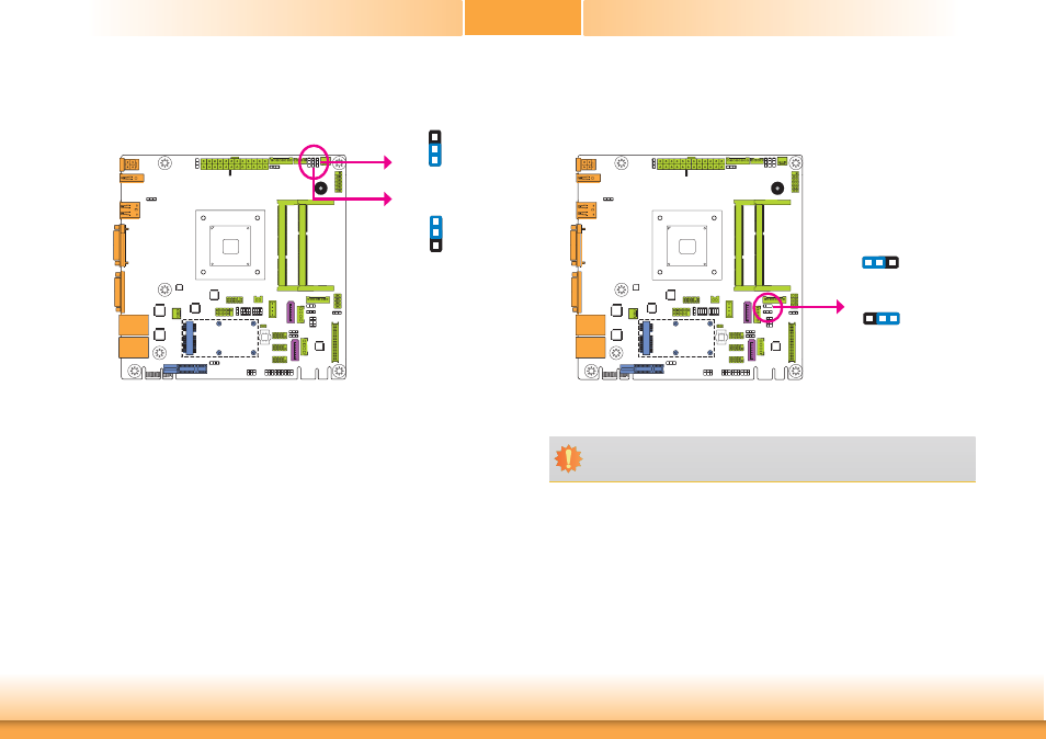
Digital I/O Output State
Based on the power level of DIO (Digital I/O) selected on JP17, JP20 (DIO pin 0-3) and JP18
(DIO pin 4-7) are used to select the state of DIO output: pull high or pull low. When selecting
pull high, the power selection will be the same as JP17’s setting.
2-3 On: GND
(default)
1-2 On: +5V or
+5V_standby
DIO 4-7
(JP18)
DIO 0-3
(JP20)
1
3
2
1
3
2
Dimming Mode Select
JP15 allows you to select the mode for the lightness control of the LVDS panel.
JP15
2-3 On: Voltage Mode
(default)
1-2 On: PWM Mode
3
1 2
3
1 2
Important:
You need to refer to your panel’s user guide to determine the type of mode (PWM or
Voltage) most appropriate for your panel.