Appendix a, Bootloader (eboot) – DFI KS200 Manual User Manual
Page 25
www.dfi.com
25
Appendix A
Appendix A Software Support
BSP (Board Support Package)
BSP
BSP Source Code
Demo Image
AM35x_BSP
COMMON_TI_V1
Tool
Manual
User Guide
TI SDCard Utility
SD Boot
NAND Boot
Project
AM35x_OSDesign
Bootloader (EBOOT)
The TS200 board boots from Flash memory using the internal boot ROM of the AM3517 ARM
Cortex-A8 processor. The bootloader architecture consists of an initial bootstrap loader called
the XLDR and a secondary loader called EBOOT. The internal boot ROM performs a minimum
hardware setup, and then copies the XLDR from the first good block of Flash memory to a
fixed location in internal SRAM. The boot ROM then jumps to the entry point of the XLDR.
The XLDR is a BSP specific bootstrap loader whose function is to do basic hardware initial-
ization and copy the second stage, full featured EBOOT from Flash memory into RAM for
execution. The XLDRsize is limited by the size of internal SRAM and does not implement any
features other than what are needed for bootstrap.
Serial User Interface
EBOOT supports a user interface over the serial port exposed on the TS200 as shown in the
following table through a RS232 connector. The actual physical CPU UART corresponding to
this connector is configured to run with the following configuration:
• 115200 baud
• 8 data bits
• 1 stop bit
• No parity
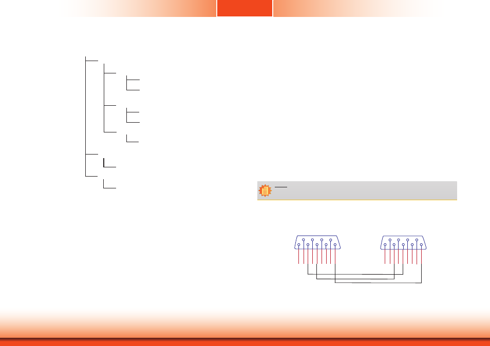
Note:
DFI RS232 standard cable (NO.332-7530404-000) or the following same specifications
cable.
RS232 Cable Pin Assignments
DB9 Connector (RS232) PC Side DB9 Connector (RS232) Product Side
Femal Femal
1
6
2
3 8 4 9 5
1
6 2 7 3 8 4 9
5
7
x
x