Rs-232c control specification – Denon DN-A7100 User Manual
Page 41
37
ENGLISH
RS-232C CONTROL SPECIFICATION
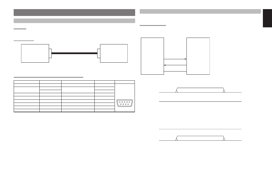
GLOBAL DESCRIPTION
OVERVIEW
A Host controller can control or watch out the product as a Slave very easily via the communication cable.
BLOCK DIAGRAM
HOST
(Controller)
RS232C cable (straight)
SLAVE
(The product)
Connector
D-SUB (9pin, male)
* The product connector is using D-SUB 9pin male.
* RS232C cable must use D-SUB 9pin female to connect the products.
INTERFACE CONNECTION SPECIFICATION OF THE PRODUCT
Processor Interface
Signal name
Connection device
D-Sub Pin
Connecter
-
N.C.
-
1
RS232C
D-SUB
(9pin,male)
1 2 3 4 5
6 7 8 9
UART
TxD (output)
RS232C Level shift driver
2
RxD (input)
3
-
N.C.
-
4
-
GND
GND
5
-
N.C.
-
6
-
N.C.
-
7
-
N.C.
-
8
-
N.C.
-
9
DETAILED DESCRIPTION
The interface specifi cation between the product and a Host controller is described below.
CONNECTION FORMAT
Physical connection
TxD
RxD
GND
RxD
TxD
GND
Host (Controller)
(Serial setting
Baud Rate
: 9600bps
Data Bits
: 8bit
Parity :
None
Stop bit
: 1bit
Handshaking : None
Slave (the product)
• Data transmission sequence from Host to Slave
/
,
TxD
RxD
RxD
TxD
Host (Controller)
Slave (The product)
1. Host starts a data transmission from TxD.
2. Host performs the data transmission of the number of required bytes, and ends a transmission.
• Data transmission sequence from Slave to Host
/
,
TxD
RxD
RxD
TxD
Host (Controller)
Slave (The product)
1. Slave starts a data transmission from TxD.
2. Slave performs the data transmission of the number of required bytes, and ends a transmission.