Section 6: relay board operation, 1 relay board description, 2 relay control keys – Daktronics All Sport 1600 Series User Manual
Page 33: Section 6, Relay board operation, Relay board description, Relay control keys
Relay Board Operation
25
Section 6:
Relay Board Operation
Sport Insert:
0G-139761 (Code 09)
The sport insert drawings are located in Appendix B. The block diagram drawings are located in
Appendix A.
Reference Drawing:
Insert, 0G-139761; A/S1600 Relay Board ................................
Refer to the information in Section 2 to start up the console and use the sport insert.
If an insert is lost or damaged, a copy of the insert drawing can be used until a replacement arrives.
If the code number for a scoreboard is unknown, refer to Appendix C. If the model number of a
scoreboard is unknown, refer to the documentation provided with the scoreboard.
6.1 Relay Board Description
The relay board consists of eight relays that can be used to control loads of up to 10 amps at
120V AC per relay.
The LCD on the console will indicate which relays are ON by displaying a 0 (zero) by the
number of that relay. Relays that are OFF will have a “^” by the number.
Making a list of what each relay number is controlling will make it easy to tell from the LCD
verifier if a specific item is ON or OFF.
6.2 Relay Control Keys
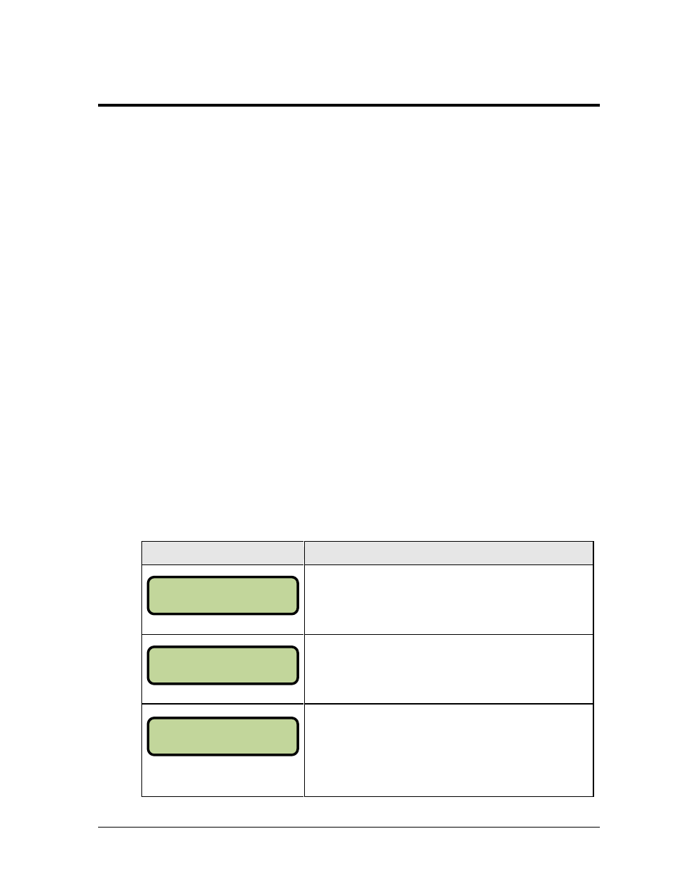
Display
Action
Press
Press
Press any key <1> through <8> once to turn on relay No. 1
through relay No. 8, respectively. Press the same key a
second time to turn off the relay.
In the example at left, only relays 3 and 6 are set to on, while
all of the other relays are set to off.
1-0 2-0 3-0 4-0
5-0 6-0 7-0 8-0
1-^ 2-^ 3-^ 4-^
5-^ 6-^ 7-^ 8-^
1-^ 2-^ 3-0 4-^
5-^ 6-0 7-^ 8-^