Using hoist lifting clips, Attaching the backbone stiffeners – Daktronics Hoist Installation Manual User Manual
Page 9
5
INSTALLATION
7
INSTALLATION
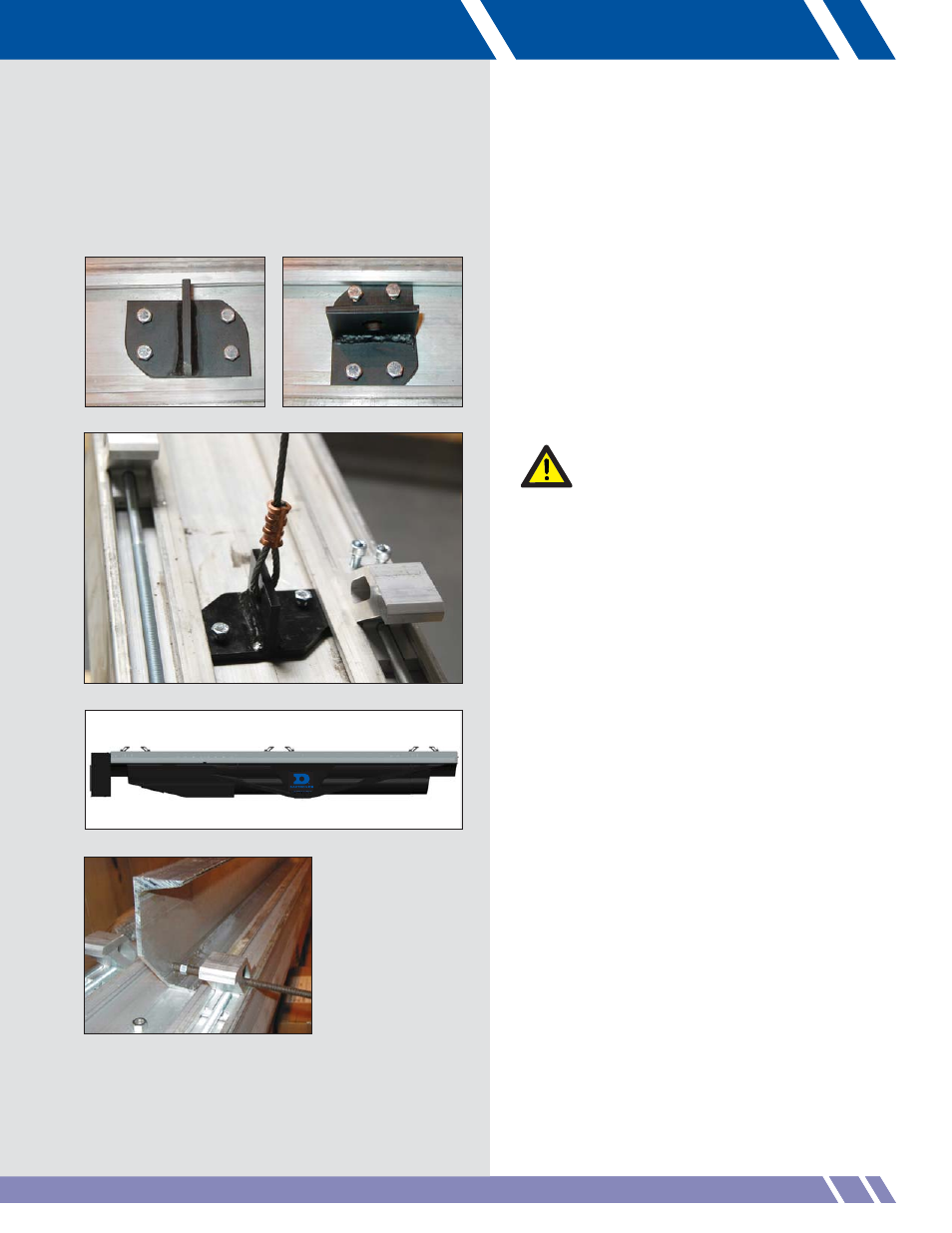
Figure 13: Lift line attached to clip
Figure 12: Set clip into the backbone channel
Figure 15: Rod through beam clamp
Figure 14: Beam clamps with hoist
Using Hoist Lifting Clips
Daktronics supplies hoist lifting clips with each
hoist installation. The hoist lifting clips install
into the backbone to connect the hoist to the
lifting cables.
Figure 12 shows a clip in the backbone
channel prior to being rotated into the proper
lifting position then locked into the channel.
Verify that the bolts are set and the clip can
not slip out of the backbone channel. Prior to
lifting, torque the bolts to 10ft/lb to secure
the clips.
Directly attach lift lines to the hoist lifting clip
with a 3/16" thimble and Nicopress swage
(Figure 13).
Each installation is unique. Pre-measure the wire
rope to be sure to have enough to go the total
distance of the lift.
Attaching the Backbone Stiffeners
Most Vortek hoist installations require the use
of backbone stiffeners. There may, however,
be three sets of beam clamps instead. Refer to
Figure 14. For 3-beam installations, skip the
following steps and begin mounting the hoist.
For 2-beam installations, there will be two
aluminum backbone stiffeners located on top of
the hoist with two 3/8" threaded rods, 4 nuts
and two steel clamps. Assemble them to the
hoist as follows:
1. Turn the backbone stiffener on edge with
the chamfered corner down and towards
the beam clamps then slide under the
center lip of the backbone. Repeat
this process for the opposing side.
2. Run the threaded rod through the beam
clamp while threading the nut onto the lead
end (Figure 15). Continue pushing the
rod into the hole on the backbone stiffener
and start threading the second nut onto the
lead end. The threaded rod will run into
and through the second beam clamp.