Troubleshooting, Troubleshooting -2, 4 troubleshooting – Daktronics MF-1000/1001/1002/1003/1004 User Manual
Page 20
4-2
Maintenance and Troubleshooting
To remove and replace a panel, follow these steps:
1. Disconnect power to the display.
2. Follow the steps in Section 4.2 to gain access to the panel.
3. Completely remove the panel/power supply circuit assembly from the display.
4. Locate the replacement panel and attach the wiring to this new panel.
5. Slide the replacement panel into the enclosure.
4.4 Troubleshooting
This section lists some symptoms that may be encountered with the display. For these
symptoms, possible cause and corrective actions are indicated. This list does not include
every possible problem, but does represent some of the more common situations that may
occur.
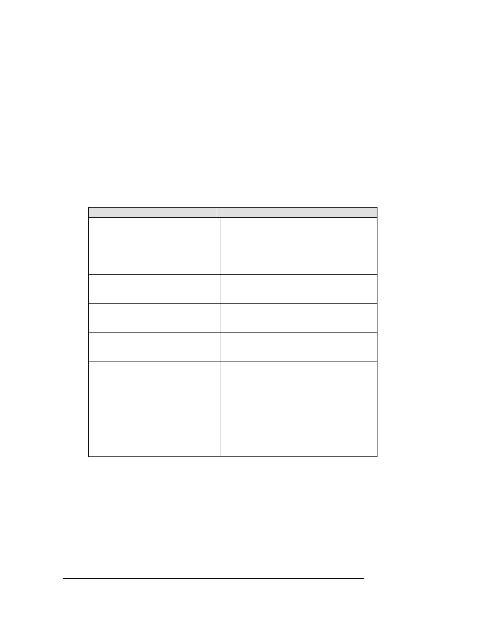
Symptom/Condition
Possible Cause or Corrective Action
Entire display fails to work
• Check for proper line voltage at termination
panel
• Has coating covering the contacts on the
board(s)
• 4-pin Mate-N-Lok is not secured properly
• Power supply malfunction
One LED set won’t light
• Has coating covering the contacts on the
board(s)
• Power supply malfunction
Both sets of LEDs are on
• Power contacts 1 and 3 are shorted
together
• Power supply malfunction
Single or multiple LEDs won’t light
• Broken leads
• Bad solder joints
• Damaged LEDs
Display brightness does not
automatically adjust
• The jumper on X1 of the power supply is
not on the middle two pins (pins 2 and 3)
• Make sure POT is rotated all the way on
(clockwise) Note: The POT sets the
maximum brightness of the auto dimming
circuit; if it isn’t all the way on, you may not
notice a change in brightness
• Verify photo cell is lined up with its
corresponding hole in the display board
• Power supply malfunction