Lightning protection, Manual control functions (switch inputs), Lightning protection -3 – Daktronics MF-1000/1001/1002/1003/1004 User Manual
Page 17: Manual control functions (switch inputs) -3, 3 lightning protection, 4 manual control functions (switch inputs)
These two power installations differ slightly, as described in the following
paragraphs:
Installation with Ground and Neutral Conductors Provided
For this type of installation, the power circuit must contain an isolated earth-ground
conductor. Under this circumstance, do not connect neutral to ground at the
disconnect or at the display. This would violate electrical codes and void the
warranty. Use a disconnect so that all hot lines and neutrals can be disconnected. The
National Electrical Code requires the use of a lockable power disconnect within sight
of or at the display.
Installation with Only a Neutral Conductor Provided
Installations where no grounding conductor is provided must comply with Article
250-32 of the National Electrical Code. If the installation in question meets all of the
requirements of Article 250-32, the following guidelines must be observed:
• Connect the grounding electrode cable at the local disconnect, never at the
display power enclosure.
• Use a disconnect that opens all the ungrounded phase conductors.
3.3 Lightning
Protection
The use of a disconnect near the display to completely cut all current-carrying lines
significantly protects the circuits against lightning damage. The National Electrical
Code also requires it. In order for this device to provide protection, the power must
be disconnected when the display is not in use.
3.4 Manual Control Functions (Switch Inputs)
Reference Drawing:
Models MF-1001, MF-1002, MF-1003, and MF-1004.. Drawing A-208524
MF-1000 Series Display Installation ............................ Drawing A-222256
This is the simplest control scheme, suitable
for low cost applications where an integrated,
remote control system is not needed. Using the
switch, a display can show ‘OPEN’,
‘CLOSED’, ‘FULL’, ‘X’, or a diagonal arrow,
depending on the model. An optional three
way switch will give a blank display as well.
Refer to Drawing A-208524.
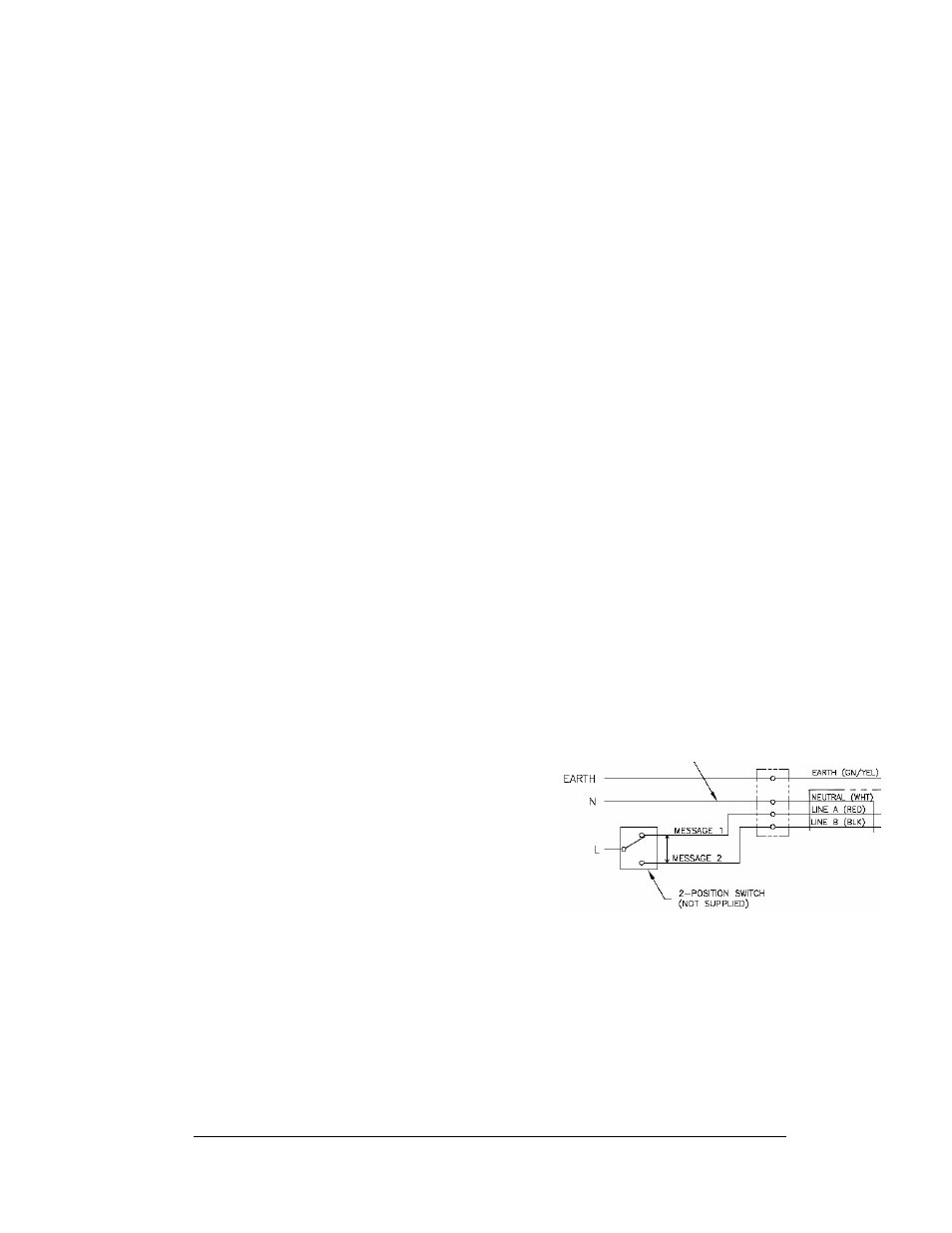
The signal will be sent using two wires from
the switch to the display. The switch is
switching 120 VAC between Lines A & B; it is not switching a signal. Refer to
Figure 3 and Drawing A-222256 for system layout.
Use 18 AWG or larger cable to connect the switch to the display as shown in
Drawing A-222256.
Figure 3: Manual Control Layout
Electrical Installation
3-3