Grounding, Power installation, Grounding -2 – Daktronics MF-1000/1001/1002/1003/1004 User Manual
Page 16
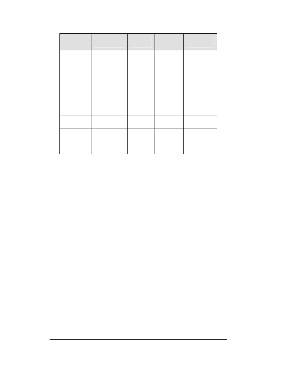
Model
Digit
Height/Color
Maximum
Wattage
Power
Amps
per Line
MF-1001-4
4" (102 mm)
Red plus green
15 W
120 VAC
0.125 A
MF-1001-6
6" (152 mm)
Red plus green
15 W
120 VAC
0.125 A
MF-1002-4
4" (102 mm)
Red plus green
15 W
120 VAC
0.125 A
MF-1002-6
6" (152 mm)
Red plus green
15 W
120 VAC
0.125 A
MF-1003-9
9" (229 mm)
Red plus green
15 W
120 VAC
0.125 A
MF-1003-14
13.5" (343 mm)
Red plus green
15 W
120 VAC
0.125 A
MF-1004-9
9" (229 mm)
Red plus green
15 W
120 VAC
0.125 A
MF-1004-14
13.5" (343 mm)
Red plus green
15 W
120 VAC
0.125 A
Grounding
Reference Drawings:
Shop Drawings ........................................................Refer to Appendix A
Displays MUST be grounded according to the provisions outlined in Article 250 of
the National Electrical Code and according to the specifications in this manual.
Daktronics requires a resistance-to-ground of 10 ohms or less.
The contractor performing the electrical installation can verify ground resistance.
Technicians from Daktronics Sales and Service offices can also provide this service.
The display system must be connected to an earth electrode installed at the display.
Proper grounding is necessary for reliable equipment operation. It also protects the
equipment from damaging electrical disturbances and lightning. The display must
be properly grounded, or the warranty will be void. Refer to the shop drawings in
Appendix A for information on where to connect the grounding wire. Connection at
the driver enclosure terminal block is illustrated at the bottom of the drawing.
The material for an earth-ground electrode differs from region to region and may
vary according to conditions present at the site. Consult the National Electrical Code
and any local electrical codes that may apply. The support structure of the display
cannot be used as an earth-ground electrode. The support is generally embedded in
concrete. If it is in earth, the steel is usually primed, or it corrodes, making it a poor
ground in either case.
Power Installation
There are two considerations for power installation: installation with ground and
neutral conductors provided, and installation with only a neutral conductor provided.
3-2 Electrical
Installation