Maintenance and troubleshooting, Service and diagnostics, Addressing – Daktronics Venus 1500 Radio – Gen 2 User Manual
Page 25: Server/client selection, Section 3, 1 service and diagnostics
Section 3:
Maintenance and Troubleshooting
This section covers service and diagnostic procedures, loopback testing, and replacement parts. The
troubleshooting chart lists symptoms that may occur with the radios along with solutions for these
issues. The replacement part section lists all the components for indoor and outdoor radio systems as
well as information on Daktronics Exchange and Repair & Return Programs.
3.1 Service and Diagnostics
Note: The following items only apply to those radios that are revision 7 and higher. The
revision of the radio is found on the same label as the part number for the radio.
Addressing
The channel address is a parameter that should be the same for all the server and client
radios in the same network. The Venus 1500 radio can operate on channels 67-74. The default
channel is 67, which corresponds to 0 on the hex dial.
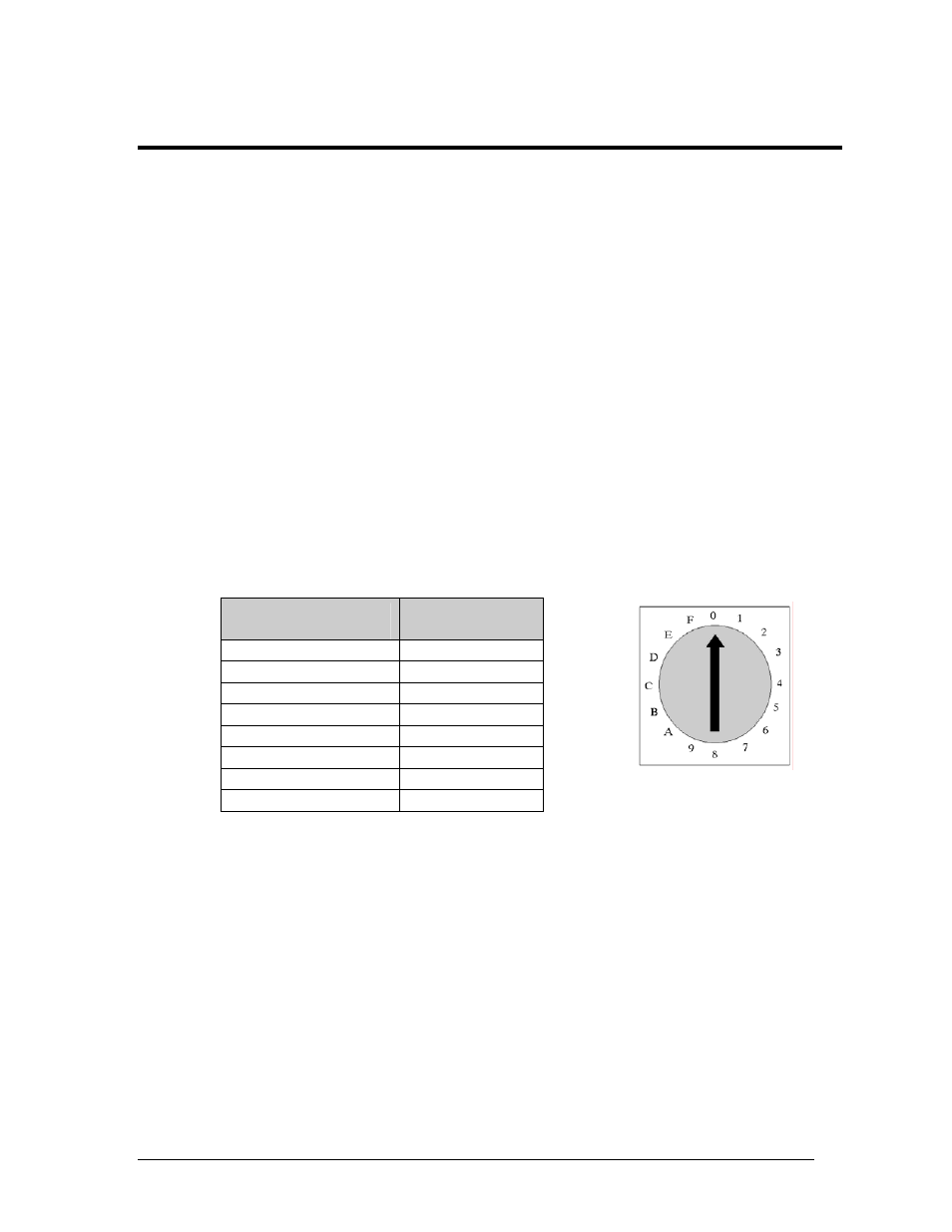
A rotary hex switch is used to set the address of the radios. The address is only read on
power up. To change the address, power down the radio, set the new address, and then
power it back up. Only the first eight numbers are used for addressing and can be set
according to the following table.
Hardware Channel
Setting (Hex Switch)
Venus 1500
Radio Channel
0 67
1 68
2 69
3 70
4 71
5 72
6 73
7 74
Figure 23: Rotary Switch
(Channel 67)
If more than one set of radios is being used in close proximity, each set can be set to their
own unique address. For example, the address of the server and the client at the first
business can be set to address 67, and the server and client at the second business can be set
to address 68.
Server/Client Selection
The same circuit board is used in both the outdoor server and client radio enclosures. The
client is selected by use of a jumper located at J2 of the radio board, as shown in Figure 24.
To select a client, the jumper should cover both pins.
The jumper is only recognized on power up. If the jumper is in the open position, the radio
will power up as a server radio. When the jumper is in the closed position, the radio will
power up as a client. Figure 24 illustrates both the closed and open positions.
Maintenance and Troubleshooting
23