Server installation via modem – Daktronics Venus 1500 Radio – Gen 2 User Manual
Page 14
Server Installation via Modem
Reference Drawings:
System Riser Diagram; Modem/QC Outdoor Radio, Gen 2 ................. Drawing A-242383
Warning: Cat-5 cable is not recommended in this installation. The distance that
power and signal can travel may vary with the use of Cat-5 cable. If Cat-5 cable is
pulled, use one pair for the ground (pin 6) and one pair for the power (pin 1). Do not
place Cat-5 cable in this application next to Ethernet communication cables or signal
loss may occur.
The modem signal system allows the control software to call another location using a dial-up
network. A signal is then sent to the server radio via a J-box/ modem at a second location.
This section will explain how to connect to the server radio from the J-box. The maximum
distance from the J-box to the server radio is 1000 feet (300 m). Refer to the system riser
Drawing A-242383, and Figure 10 for more information.
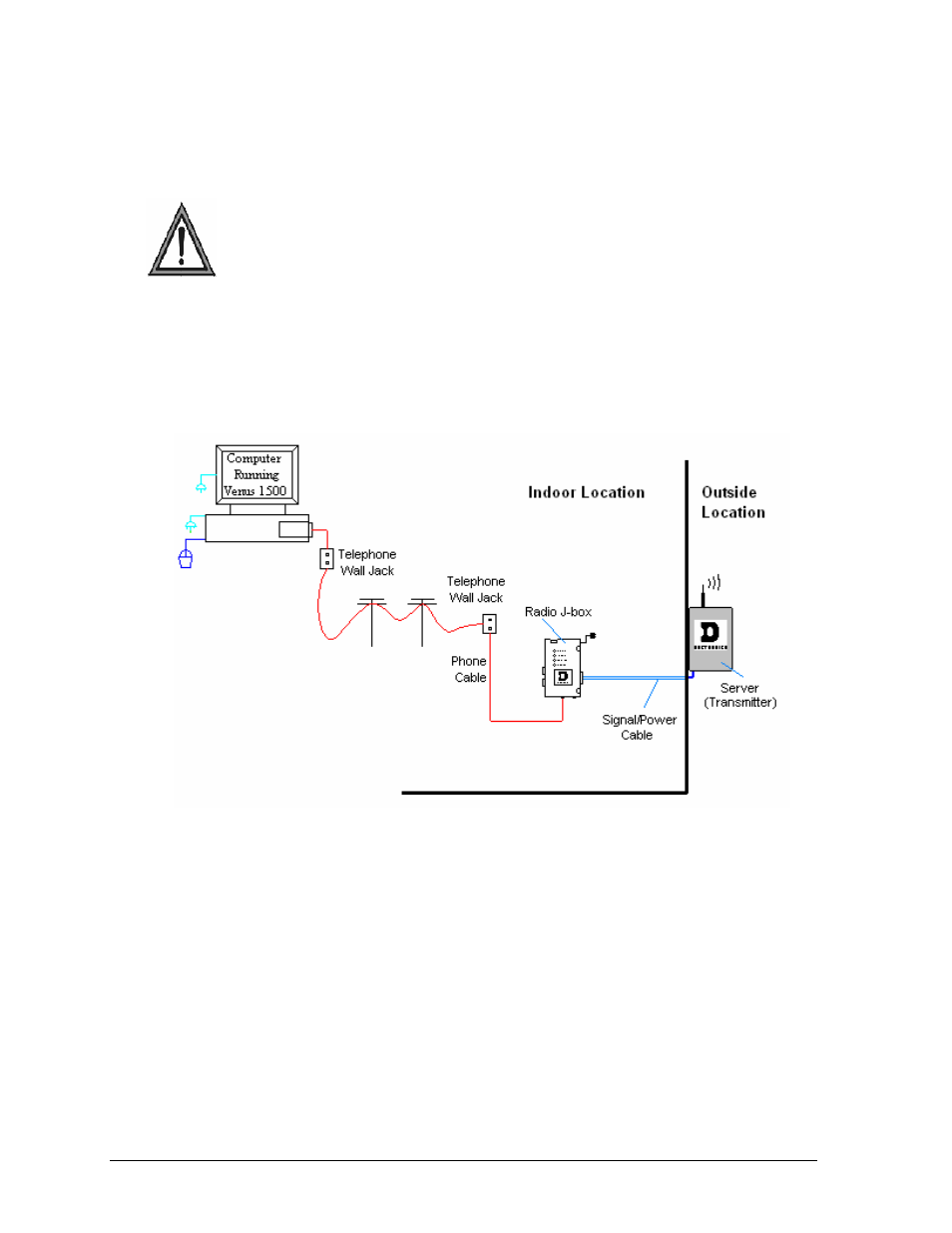
Figure 10: Remote Location to Server Radio via Modem
The following directions are provided for connecting from the computer to the server radio:
1. Using a flipped, 6-conductor, 26 AWG, stranded silver satin cable, plug one end of
the RJ-11 cable into the telephone wall jack. Plug the other end into the J-
box/modem, at the jack labeled “Phone Line Connection”.
2. Plug the J-box’s power adaptor into a 120VAC grounded outlet. Plug the jack into
the J-box/modem at the port labeled 12V power IN.
3. Connect power/signal cables as follows:
• Run the 6-conductor, 18 AWG stranded cable from the J-box/modem to the
server radio.
• Connect the wires at the phoenix plug (labeled RS-422 Out to Radio) on the J-
box/modem.
• Connect the wires to phoenix plug labeled TB2 (RS-422 IN) on the server radio
board. The cable is pinned one-to-one.
Installation Guidelines
12