Daktronics FuelightTM FL-3000 and FL-4500 Petroleum Display User Manual
Fuelight, Installation, Power connection
Fuelight
TM
FL-3000 and FL-4500
Petroleum Display Installation Quick Guide
Page 1 of 4
DD2238842 Rev 04
26 June 2014
PO Box 5128 201 Daktronics Drive, Brookings, SD 57006-5128
tel: 800-325-8766 fax: 605-697-4700
Installation
1. Mount the display into the sign structure using the provided holes in the mounting
flange. Refer to
Note: Do not drill holes into the display face. This will void the warranty.
2. Use appropriate screws or other hardware to secure the sign to the structure.
Note: The display is front ventilated. Do
not block the display face in any way.
This may void the display warranty.
Power Connection
1. Use the provided knockouts on the back
of the display for power entrance.
2. Use a flat-head screwdriver to turn the latches and access the interior of the
display.
3. Connect the primary power hot (black) and neutral (white) wires to the wires
coming from the power supply. Refer to
Note: Refer to the display shop drawing for power requirements.
4. Connect the primary power ground (green) wire to the ground bar next to the
power supply.
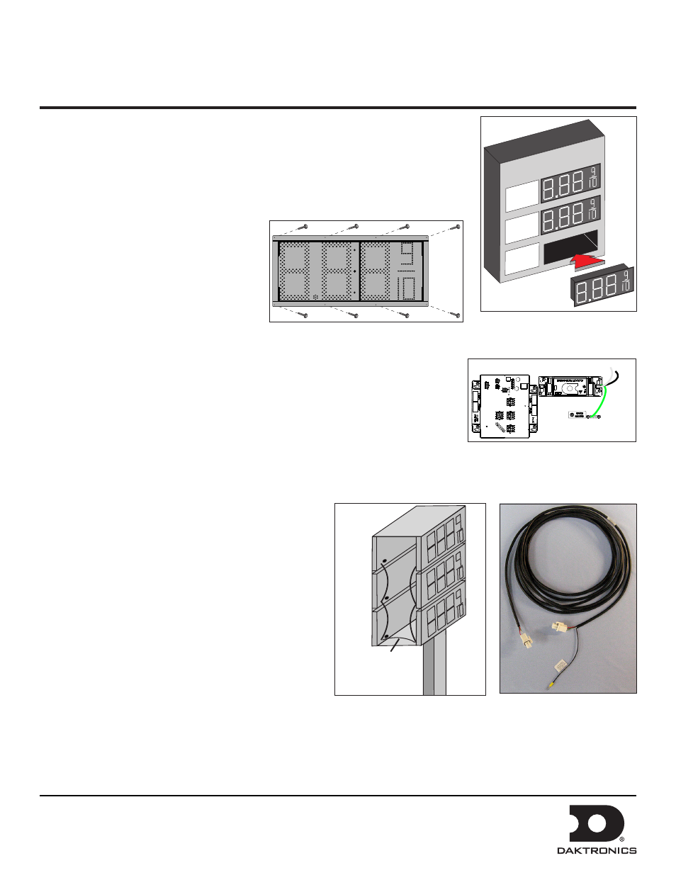
Display Interconnections
Signal travels from the host driver jack J9 to additional
display drivers through the Line-to-Line cable. Line-to-line
connections are made using jacks J9 and J10 on the driver.
The preferred cable routing has signal leaving each driver
from jack J9 and entering the next driver on jack J10
Each time you connect the line-to-line cable to J9, you
must also connect the drain wire to the upper-left stud
that holds the driver in place.
1. Use provided knockouts on the back of the display for
signal entrance and exit. Refer to
2. Install the provided bushing at the knockout location.
3. Connect the provided line-to-line cable, shown in Figure 5, to host driver jack J9. The host driver can be identified by
having the communication option attached to jack J16.
Figure 1: Securing Digit Cabinet
daktronics
CORNER GAS
UNL
REG
DSL
Figure 2: Inserting Digits into
Cabinet
Ground (Green)
Hot
(Black)
Neutral (White)
Power Supply
Driver
Figure 3: Power Wiring
Line 2
Line 3
Line 1
2
3
1
Signal Wire
Figure 4: Line-to-Line Details
Figure 5: Line-to-Line Cable