2 single-court scoreboard mounting, Suspension mounting, Single-court scoreboard mounting – Daktronics TN-2501 Tuff Sport Indoor LED Tennis Scoreboard User Manual
Page 10
4
Mechanical Installation
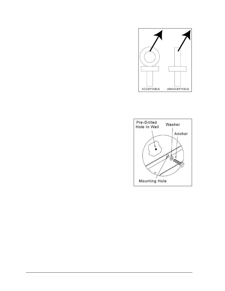
Exceeding load angles or weight limits could cause the
bolts in the scoreboard cabinet to buckle, resulting in
serious damage to the scoreboard or injury to personnel.
Also, loads should be applied directly in the plane of the
eyebolt as shown in Figure 4.
Note: Daktronics assumes no liability for damages
resulting from incorrect setup or lifting methods.
Eyebolts are intended for lifting only. Do not attempt
to permanently support the display by the eyebolts
without the suspension mounting kit.
Small Daktronics scoreboards are not equipped with
eyebolts, and instead use two lifting straps that encircle
the scoreboard. It is recommended to use a spreader bar
with the straps.
2.2 Single-Court Scoreboard Mounting
1. Use the eyebolt(s) at the top of the scoreboard
frame to lift the display into position for mounting.
2. Secure the display to the wall by attaching
mounting hardware through all holes on the top
and bottom rear flanges of the display to a pre-
drilled hole in the wall (Figure 5).
For mounting locations, weights and hardware
suggestions, refer to the model-specific mechanical
specification drawings attached to the product
specification sheets listed in Appendix A.
Due to the variety of wall materials used in sports
facilities, Daktronics cannot anticipate a user’s
individual installation needs or provide mounting
hardware suitable for every installation. Choose a
method of installation that will safely support the
weight of the display.
Suspension Mounting
Rather than being mounted to the wall, single-court scoreboards may be suspended using a
special lift eye mounting kit. Refer to Drawing A-1130959 in Appendix B for more
information. Always contact Daktronics about any installation that involves permanently
suspending the scoreboard.
Figure 4: Eyebolt Plane Load
Figure 5: Wall Mounting
- TN-2503 Tuff Sport Indoor LED Tennis Scoreboard TN-2504 Tuff Sport Indoor LED Tennis Scoreboard TN-2505 Tuff Sport Indoor LED Tennis Scoreboard TN-2560 Tuff Sport Indoor LED Tennis Scoreboard TN-2561 Tuff Sport Indoor LED Tennis Scoreboard TN-2562 Tuff Sport Indoor LED Tennis Scoreboard TN-2563 Tuff Sport Indoor LED Tennis Scoreboard