Ba-2029, Fb-2028 – Daktronics P1647 Multi-Section Outdoor LED Scoreboard User Manual
Page 24
18
Electrical Installation
BA-2029
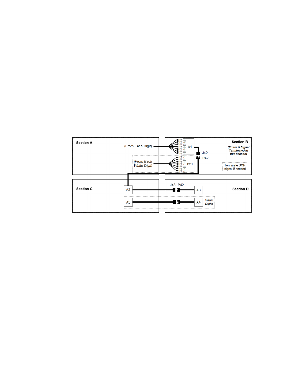
Open the appropriate access panel on the bottom-left cabinet (Section C) to locate the coiled
bundles of interconnect cable coming from the driver, then route and connect the cables as
described below and shown in Figure 23.
Note: Additional panels may be opened for easier access when routing the cable.
1. There are seven 9-pin digit harnesses (P1–P7) in the upper-left cabinet (Section A)
that must be routed into the upper-right cabinet (Section B) and connected to the
mating J1–J7 jacks on the A1 driver. For scoreboards with white digits, 2-pin cables
must also be routed and connected to the mating J1–J7 jacks on the PS1 power supply.
2. There are two separate interconnect cables in Section C:
a. Route the 5-pin interconnect cable with the P42 plug up into Section A first then
over into Section B, and connect it to the J42 jack on the A1 driver.
b. Route the 5-pin interconnect cable with the J43 jack over into the bottom-right
cabinet (Section D), and connect it to another interconnect cable with the P42 plug.
FB-2028
Open the appropriate access panels on the upper-left (Section A) and bottom-left cabinet
(Section C) to locate the coiled bundles of interconnect cable coming from the drivers.
Refer to Figure 24.
Note: Additional panels may be opened for easier access when routing the cable.
1. Route the 5-pin interconnect cable with the J43 jack from Section C over into the
bottom-right cabinet (Section D) and connect it to the P43 plug on the A4 driver.
2. There will also be two separate interconnect cables in Section A:
a. Route the 5-pin interconnect cable with the J43 jack over into the upper-right
cabinet (Section B) and connect it to the P42 plug on another interconnect cable
coming from the A2 driver.
b. Route the 5-pin (two wire, signal only) cable with the P42 plug down into Section
C, and connect it to the J42A jack on a Y-cable coming from the A3 driver.
Note: The FB-2028 can be thought of as two scoreboards stacked on top of each other.
Both the A1 and A3 drivers require power termination, while only A3 requires signal
termination from the control location. Refer to Section 3.2 and Section 3.4.
Figure 23: Power/Signal Connection
– Four Sections, BA-2029 (Front View)