Four-section models, Ba-2026 & ba-2028 – Daktronics P1647 Multi-Section Outdoor LED Scoreboard User Manual
Page 23
Electrical Installation
17
For the BA-1518 with red/amber digits, there are five 9-pin digit harnesses (P1–P4 &
P15) in the upper section that must be routed down into the bottom section and
plugged into the mating jacks (J1–J4 & J15) on the A1 driver. For the BA-1518 with
white digits, there is a single 5-pin interconnect cable coiled in the upper section that
must be routed down into the bottom section and connected to the J42B jack on a Y-
cable coming from the A2 driver.
Four-Section Models
BA-2026 & BA-2028
Open the appropriate access panel on the bottom-left cabinet (Section C) to locate the coiled
bundles of interconnect cable coming from the driver, then route and connect the cables as
described below and shown in Figure 22.
Note: Additional panels may be opened for easier access when routing the cable.
1. There are four 9-pin digit harnesses (P8–P11) in the upper-right cabinet (Section B)
that must be routed into the upper-left cabinet (Section A) and connected to the mating
J8–J11 jacks on the A1 driver. For scoreboards with white digits, 2-pin cables must also
be routed and connected to the mating J8–J11 jacks on the PS1 power supply.
2. There are also two separate interconnect cables in Section C:
a. Route the 5-pin interconnect cable with the P42 plug up into Section A, and
connect it to the J42 jack on the A1 driver.
b. Route the 5-pin interconnect cable with the J43 jack over into the bottom-right
cabinet (Section D), and connect it to another interconnect cable with the P42 plug.
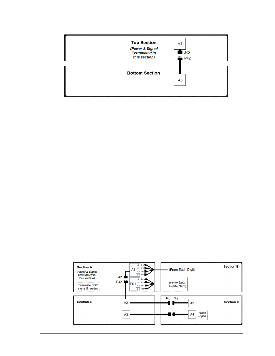
Figure 21: Power/Signal Connection
– Two Sections, BA-2025 & BA-2027 (Front View)
Figure 22: Power/Signal Connection
– Four Sections, BA-2026 & BA-2028 (Front View)