Radio settings, 4 signal connection, Fiber optic – Daktronics P1647 Multi-Section Outdoor LED Scoreboard User Manual
Page 21: Signal connection
Electrical Installation
15
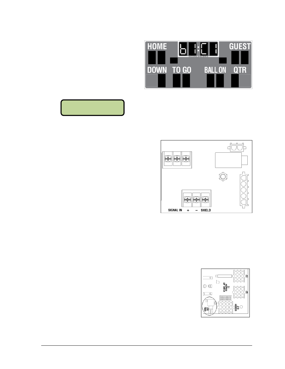
Radio Settings
If a radio receiver is installed (see
Section 5.3), the radio Broadcast
settings (“b1”) and Channel settings
(“C1”) will be displayed in the clock
digits or Home and Guest scores
during the POST (Figure 16). These
values must match the settings in the
control console (refer to Figure 17 and
the manual listed in Section 1.1).
3.4 Signal Connection
For wired setups, route signal cable through
the conduit knockout on the rear of the
scoreboard to the signal surge arrestor card
(Figure 18), located just above the power
termination block in the driver enclosure.
At the SIGNAL IN terminal block, connect red
signal wire to positive (+) and black signal wire
to negative (–).
Note: Be sure to properly connect the
shield (silver) wire to the SHIELD terminal.
To connect signal to auxiliary displays, such as delay of game clocks, route signal wire from
SIGNAL OUT on the main terminal block (Figure 14) of the primary scoreboard to SIGNAL IN
on the signal card of the auxiliary scoreboard.
For signal cable, Daktronics recommends, as a minimum, single-pair, shielded cable, 22 AWG
(part # W-1077). Two-pair shielded cable (part # W-1234) is preferred.
Fiber Optic
Another common signal communication method is fiber optic
cabling. A minimum cabling of multi-mode, 62.5/125 um, and
2-core fiber cable is recommended (part # W-1242). The fiber optic
cable is terminated to a male ST-type connector and plugged into
the mating J26 FIBER jack on the driver (Figure 19). This method
requires a signal converter between the All Sport console’s
scoreboard output and the fiber optic cable (not provided by
Daktronics).
Figure 16: Radio Settings (Clock)
Figure 17: Radio Settings (Console)
Figure 18: Signal Surge Arrestor Card
Figure 19: Driver Fiber
Connection Location
RADI O SETTI NGS
BCAST 1 CHAN 01