2 scoreboard mounting, Scoreboard mounting – Daktronics P1647 Multi-Section Outdoor LED Scoreboard User Manual
Page 10
4
Mechanical Installation
Do NOT attempt to lift the display if the angle is less than
45°. Exceeding load angles or weight limits could cause
the bolts in the scoreboard cabinet to buckle, resulting in
serious damage to the scoreboard or injury to personnel.
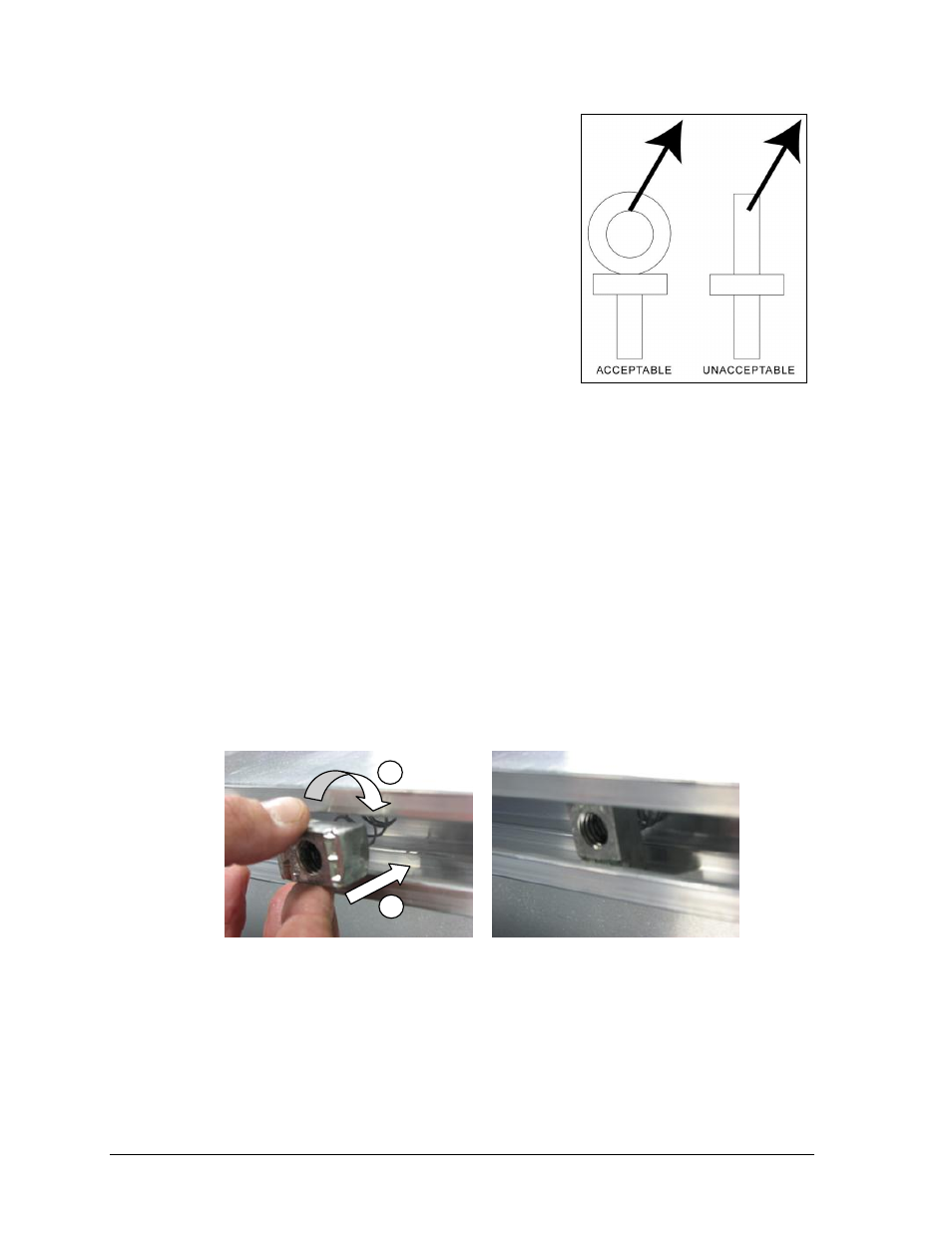
Also, loads should be applied directly in the plane of the
eyebolt as shown in Figure 4.
Note: Daktronics assumes no liability for damages
resulting from incorrect setup or lifting methods.
Eyebolts are intended for lifting only. Do not attempt
to permanently support the display by the eyebolts.
In typical multi-section installations, the lower scoreboard
is installed first and secured to the support beams.
The upper section is then placed atop or above the lower
section and attached to the beams. Refer to Section 3.5 for
more information on the power/signal connections between sections.
If installers remove the eyebolts, plug the holes with bolts and the rubber washers that are
used with the eyebolts. Apply silicone or another waterproof sealant to the eyebolt openings.
Also inspect the top and sides of the display for any other holes or openings that may allow
moisture to enter the display and plug and seal those openings.
2.2 Scoreboard Mounting
Two standard mounting methods are available for Daktronics outdoor scoreboards.
Both methods require spring nuts to be inserted into the rear channel of the scoreboard:
1. Insert spring nuts into the top and bottom scoreboard channels. Twist the spring nuts
until they are perpendicular to the scoreboard channel (Figure 5).
Note: Each scoreboard section require four spring nuts per beam (two at the top and two
at the bottom).
2. Measure the beam spacing and position a spring nut on either side of the beams.
Once the spring nuts are in place, refer to the appropriate section below for the type of
mounting hardware provided with the scoreboard.
Figure 4: Eyebolt Plane Load
1) Insert into channel 2) Twist Correct spring nut position
Figure 5: Spring Nut Insertion
1
2