Clamping angles – Daktronics DA-1000 Outdoor Decorative Accent User Manual
Page 16
10
Installation
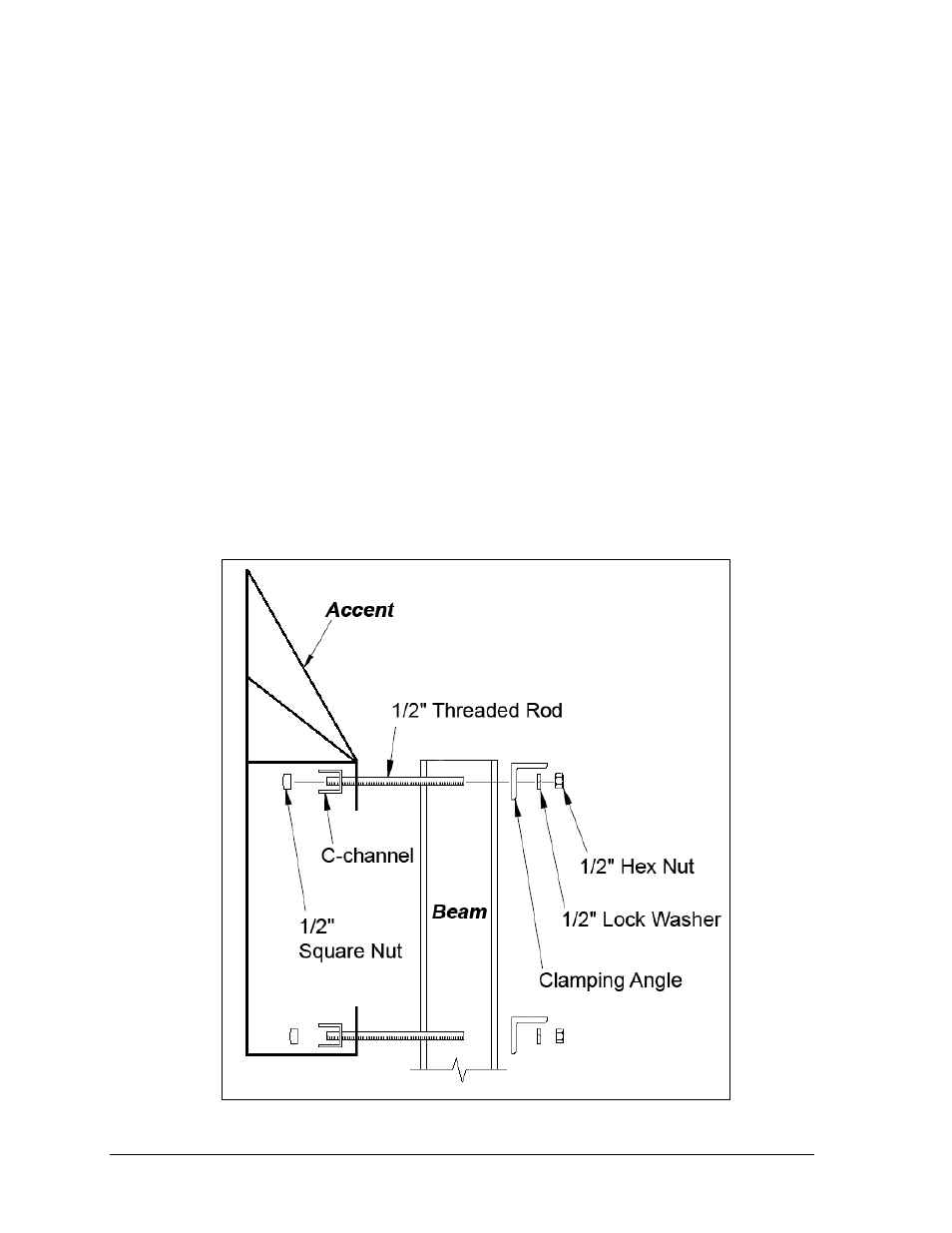
Clamping Angles
Mounting hardware includes C-channels; rear clamping angles;
1
/
2
-13 x 15" threaded rods;
and
1
/
2
" nuts and lock washers. Refer to Figure 10 and Drawing A-52187 in Appendix A.
Note: The threaded rods do not pass through the beams; they run along both sides.
1. Position the accent at the front of the beams, and lift it to the desired height.
2. Using a clamping angle as a template, drill
9
/
16
" holes in the upper rear flange of the
accent cabinet where the C-channel support will be placed.
3. Position a C-channel inside the accent cabinet along the rear flange as shown in
4. Place
1
/
2
" square nuts inside the C-channel, and thread the rods through the rear
flange of the accent cabinet and the C-channel.
5. Slide clamping angles over the other ends of the threaded rods and loosely install the
washers and nuts.
6. Make final adjustments in the positioning of the accent to ensure it is flush and level,
and firmly tighten all of the
1
/
2
" hex nuts.
7. Repeat steps 2-6 for the other mounting hardware set on the bottom rear flange of the
accent cabinet.
8. Repeat step 7 for all beams.
9. Remove the lift eyebolts and fill remaining holes with silicone.
Figure 10: Dome Accent Mounting with Clamping Angles, Side View