6 shot clock signal connection, Shot clock signal connection – Daktronics BB-2101 Tuff Sport Basketball LED Scoreboard User Manual
Page 23
Electrical Installation
17
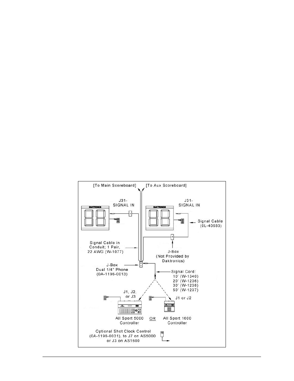
4.6 Shot Clock Signal Connection
For permanent shot/game clock installations (Figure 12), signal wiring may be routed from a
J-box at the control console end and terminated at another J-box by the display, similar to the
method used for scoreboards and stat displays. See also Drawings A-124688 and A-125415 in
Appendix E.
1. At a minimum, use a paired, 22 AWG shielded cable (Daktronics part # W-1077) and
connect the cable to a dual
1
/
4
" J-box at the control console end.
2. Route the cable from the J-box on the control console end to a J-box near the display.
3. Install the
1
/
4
" phone plug (Daktronics part # 0L-40683) to the shot clock end of the
cable. Be sure to connect the cable shielding only in the J-box on this end.
Note: DO NOT connect cable shielding at the J-box near the control console.
4. Route the
1
/
4
" phone plug from the J-box near the display to the first shot clock.
5. Insert the plug into the J31 – SIGNAL IN jack located on the side of the shot clock.
6. Repeat steps 1-5 for the other shot clock.
7. Connect a signal cable from the J-box to the J1, J2, or J3 jack on the back of the All
Sport 5000 console or J1/J2 on the All Sport 1600 console.
If using an optional Shot Clock Start/Stop Switch (Daktronics part # 0A-1196-0031),
connect it to the J7 jack on the All Sport 5000 or J3 on the All Sport 1600.
Figure 12: Shot Clock Installation
- BB-2103 Tuff Sport Basketball LED Scoreboard BB-2105 Tuff Sport Basketball LED Scoreboard BB-2107 Tuff Sport Basketball LED Scoreboard BB-2109 Tuff Sport Basketball LED Scoreboard BB-2111 Tuff Sport Basketball LED Scoreboard BB-2114 Tuff Sport Basketball LED Scoreboard BB-2115 Tuff Sport Basketball LED Scoreboard BB-2116 Tuff Sport Basketball LED Scoreboard BB-2117 Tuff Sport Basketball LED Scoreboard BB-2119 Tuff Sport Basketball LED Scoreboard BB-2120 Tuff Sport Basketball LED Scoreboard BB-2143 Tuff Sport Basketball LED Scoreboard BB-2142 Tuff Sport Basketball LED Scoreboard SD-2107 Tuff Sport Basketball LED Scoreboard BB-2137 Tuff Sport Basketball LED Scoreboard SD-2106 Tuff Sport Basketball LED Scoreboard BB-2132 Tuff Sport Basketball LED Scoreboard SD-2104 Tuff Sport Basketball LED Scoreboard BB-2131 Tuff Sport Basketball LED Scoreboard SD-2103 Tuff Sport Basketball LED Scoreboard BB-2130 Tuff Sport Basketball LED Scoreboard SD-2102 Tuff Sport Basketball LED Scoreboard BB-2128 Tuff Sport Basketball LED Scoreboard SD-2101 Tuff Sport Basketball LED Scoreboard BB-2127 Tuff Sport Basketball LED Scoreboard PN-2101 Tuff Sport Basketball LED Scoreboard BB-2125 Tuff Sport Basketball LED Scoreboard BB-2155 Tuff Sport Basketball LED Scoreboard BB-2123 Tuff Sport Basketball LED Scoreboard BB-2153 Tuff Sport Basketball LED Scoreboard BB-2122 Tuff Sport Basketball LED Scoreboard BB-2152 Tuff Sport Basketball LED Scoreboard BB-2121 Tuff Sport Basketball LED Scoreboard BB-2144 Tuff Sport Basketball LED Scoreboard BB-3101 ColorSmart Basketball LED Scoreboard BB-3103 ColorSmart Basketball LED Scoreboard BB-3105 ColorSmart Basketball LED Scoreboard BB-3107 ColorSmart Basketball LED Scoreboard BB-3114 ColorSmart Basketball LED Scoreboard BB-3142 ColorSmart Basketball LED Scoreboard BB-3125 ColorSmart Basketball LED Scoreboard BB-3123 ColorSmart Basketball LED Scoreboard BB-3121 ColorSmart Basketball LED Scoreboard BB-3115 ColorSmart Basketball LED Scoreboard SD-3103 ColorSmart Basketball LED Scoreboard SD-3102 ColorSmart Basketball LED Scoreboard SD-3101 ColorSmart Basketball LED Scoreboard BB-3101 ColorSmart Indoor LED Scoreboard BB-3102 ColorSmart Indoor LED Scoreboard BB-3103 ColorSmart Indoor LED Scoreboard BB-3104 ColorSmart Indoor LED Scoreboard BB-3105 ColorSmart Indoor LED Scoreboard BB-3106 ColorSmart Indoor LED Scoreboard BB-3107 ColorSmart Indoor LED Scoreboard BB-3108 ColorSmart Indoor LED Scoreboard BB-3142 ColorSmart Indoor LED Scoreboard BB-3126 ColorSmart Indoor LED Scoreboard BB-3125 ColorSmart Indoor LED Scoreboard BB-3124 ColorSmart Indoor LED Scoreboard SD-3103 ColorSmart Indoor LED Scoreboard BB-3123 ColorSmart Indoor LED Scoreboard SD-3102 ColorSmart Indoor LED Scoreboard SD-3101 ColorSmart Indoor LED Scoreboard BB-3146 ColorSmart Indoor LED Scoreboard BB-3147 ColorSmart Indoor LED Scoreboard BB-3121 ColorSmart Indoor LED Scoreboard BB-3115 ColorSmart Indoor LED Scoreboard BB-3114 ColorSmart Indoor LED Scoreboard TN-2501 Tuff Sport Indoor Tennis LED Scoreboard TN-2503 Tuff Sport Indoor Tennis LED Scoreboard TN-2504 Tuff Sport Indoor Tennis LED Scoreboard TN-2505 Tuff Sport Indoor Tennis LED Scoreboard TN-2550 Tuff Sport Indoor Tennis LED Scoreboard TN-2551 Tuff Sport Indoor Tennis LED Scoreboard TN-2552 Tuff Sport Indoor Tennis LED Scoreboard TN-2553 Tuff Sport Indoor Tennis LED Scoreboard TN-2560 Tuff Sport Indoor Multi-Court Tennis LED Scoreboard TN-2561 Tuff Sport Indoor Multi-Court Tennis LED Scoreboard TN-2562 Tuff Sport Indoor Multi-Court Tennis LED Scoreboard TN-2563 Tuff Sport Indoor Multi-Court Tennis LED Scoreboard H-2101 Tuff Sport Hockey LED Scoreboard H-2102 Tuff Sport Hockey LED Scoreboard H-2103 Tuff Sport Hockey LED Scoreboard H-2104 Tuff Sport Hockey LED Scoreboard H-2106 Tuff Sport Hockey LED Scoreboard H-2115 Tuff Sport Hockey LED Scoreboard H-2114 Tuff Sport Hockey LED Scoreboard H-2111 Tuff Sport Hockey LED Scoreboard H-2108 Tuff Sport Hockey LED Scoreboard BB-2102 Tuff Sport Four-Sided Basketball LED Scoreboard BB-2104 Tuff Sport Four-Sided Basketball LED Scoreboard BB-2106 Tuff Sport Four-Sided Basketball LED Scoreboard BB-2108 Tuff Sport Four-Sided Basketball LED Scoreboard BB-2124 Tuff Sport Four-Sided Basketball LED Scoreboard BB-2156 Tuff Sport Four-Sided Basketball LED Scoreboard BB-2154 Tuff Sport Four-Sided Basketball LED Scoreboard BB-2147 Tuff Sport Four-Sided Basketball LED Scoreboard BB-2146 Tuff Sport Four-Sided Basketball LED Scoreboard BB-2126 Tuff Sport Four-Sided Basketball LED Scoreboard BB-3102 ColorSmart Four-Sided Basketball LED Scoreboard BB-3104 ColorSmart Four-Sided Basketball LED Scoreboard BB-3106 ColorSmart Four-Sided Basketball LED Scoreboard BB-3108 ColorSmart Four-Sided Basketball LED Scoreboard BB-3147 ColorSmart Four-Sided Basketball LED Scoreboard BB-3146 ColorSmart Four-Sided Basketball LED Scoreboard BB-3124 ColorSmart Four-Sided Basketball LED Scoreboard BB-3126 ColorSmart Four-Sided Basketball LED Scoreboard VB-2101 Tuff Sport Volleyball LED Scoreboard H-2105 Tuff Sport Four-Sided Hockey LED Scoreboard H-2107 Tuff Sport Four-Sided Hockey LED Scoreboard H-2109 Tuff Sport Four-Sided Hockey LED Scoreboard H-2112 Tuff Sport Four-Sided Hockey LED Scoreboard