Setting the driver address (all sport 5000 only), 4 schematics, 5 replacement parts list – Daktronics LED End-of-Period Basketball Lighting User Manual
Page 15: 6 routine/preventative maintenance, Schematics, Replacement parts list, Routine/preventative maintenance
Maintenance & Troubleshooting
9
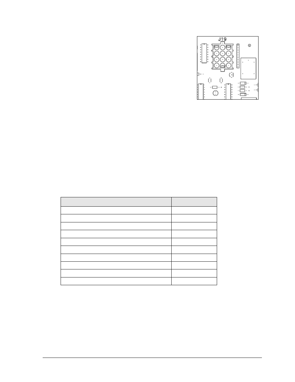
Setting the Driver Address (All Sport 5000 Only)
Since the same LED drivers can be used for many scoreboard
models, each driver must be set to receive the correct signal
input, or address, for the model being used. This address is
set with jumper wires in a 12-pin plug which mates with jack
J19 on the driver (Figure 4).
It may be possible to reuse the same address plug from the
driver that was replaced. If not, be sure to contact Daktronics
to order an address 1 plug (part # 0A-1150-0122).
4.4 Schematics
Reference Drawings:
Schem: LED Light Strip Controller ......................................................... Drawing A-176075
For advanced troubleshooting and repair, it may be necessary to consult a schematic
drawing. Drawing A-176075 in Appendix A represents the schematic diagrams for the LED
light strip controller. The schematic includes power and signal inputs and all internal wiring
for the lighting system.
4.5 Replacement Parts List
Refer to the following table for Daktronics scoreboard replacement parts.
Description
Daktronics Part #
Address 1 plug
0A-1150-0122
LED driver, 4-column
0P-1150-0130
Cable; 3-pin XLR male to female, 30'
0A-1230-0090
Light strip, full mod, amber (24 sec violation)
0A-1230-0135
Light strip, half mod, amber (24 sec violation)
0A-1230-0136
14.375" Red LED l
ight strip (scorer’s table)
0P-1230-0137
Light strip, full mod, red (standard backboard)
0A-1230-0141
Light strip, half mod, red (standard backboard)
0A-1230-0142
48" light strip (
scorer’s table clock stopped indicator)
0A-1237-1313
Transformer, 120P/16S, 6.3 A
T-1066
4.6 Routine/Preventative Maintenance
Perform an annual visual inspection of each display and check the following:
Check and tighten fasteners or replace them as required.
Check the electrical components for proper connection and any signs of corrosion.
Figure 4: Address Jack J19