Setting the driver address, 4 schematics, 5 replacement parts list – Daktronics BB-2135 Backboard LED Light Strip User Manual
Page 13: 6 routine/preventative maintenance, Schematics, Replacement parts list, Routine/preventative maintenance
Maintenance & Troubleshooting
7
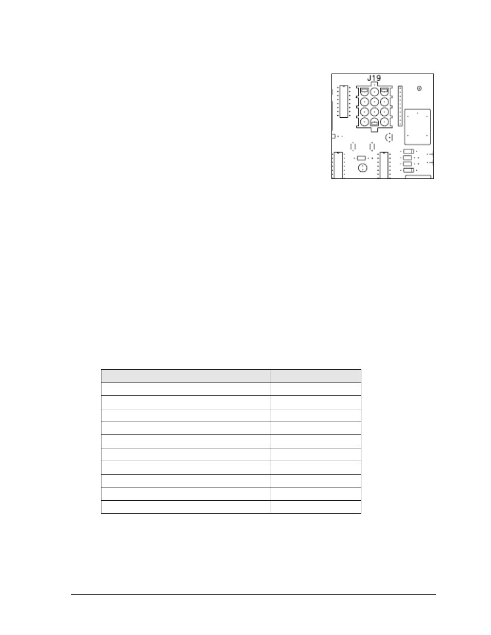
Setting the Driver Address
Since the same LED drivers can be used for many scoreboard
models, each driver must be set to receive the correct signal
input, or address, for the model being used. This address is set
with jumper wires in a 12-pin plug which mates with jack J19
on the driver (Figure 4).
It may be possible to reuse the same address plug from the
driver that was replaced. If not, use an Address 1 plug (part #
0A-1150-0122) for All Sport 5000 controlled light strips. For All
Sport 5500 controlled light strips (ColorSmart scoreboards),
use a fully-loaded address plug (part # 0A-1150-0064) set to
Address 2, meaning all wires except red should be cut.
3.4 Schematics
Reference Drawings:
Schem: LED Light Strip Controller ......................................................... Drawing A-176075
Schem: MCAST LED Light Strip Controller ............................................ Drawing A-314188
For advanced troubleshooting and repair, it may be necessary to consult a schematic
drawing. Drawing A-176075 and Drawing A-314188 in Appendix A represent the schematic
diagrams for the LED light strip controller. The schematic includes power and signal inputs
and all internal wiring for the lighting system.
3.5 Replacement Parts List
Refer to the following table for Daktronics scoreboard replacement parts.
Description
Daktronics Part #
12-pin address plug (MCAST/ColorSmart)
0A-1150-0064
Address 1 plug
0A-1150-0122
LED driver, 4-column
0P-1150-0130
Cable; 3-pin XLR male to female, 30'
0A-1230-0090
18" Light Strip (bottom)
0A-1237-0626
29" Light Strip (side)
0A-1237-0627
62" Light Strip (top)
0A-1237-0628
35" Light Strip (side)
0A-1237-0862
LED driver, 4-column (MCAST/ColorSmart)
0P-1388-0101
Transformer, 120P/16S, 6.3 A
T-1066
3.6 Routine/Preventative Maintenance
Perform an annual visual inspection of each display and check the following:
Check and tighten fasteners or replace them as required.
Check the electrical components for proper connection and any signs of corrosion.
Figure 4: Address Jack J19