Mounting, Termination possibility – Contemporary Control Systems BACnet Cube I/O NG-4 Gray User Manual
Page 2
METZ CONNECT GmbH
Im Tal 2 | 78176 Blumberg | Germany | Phone +49 7702 533-0 | Fax +49 7702 533-433
Mounting instruction see www.metz-connect.com
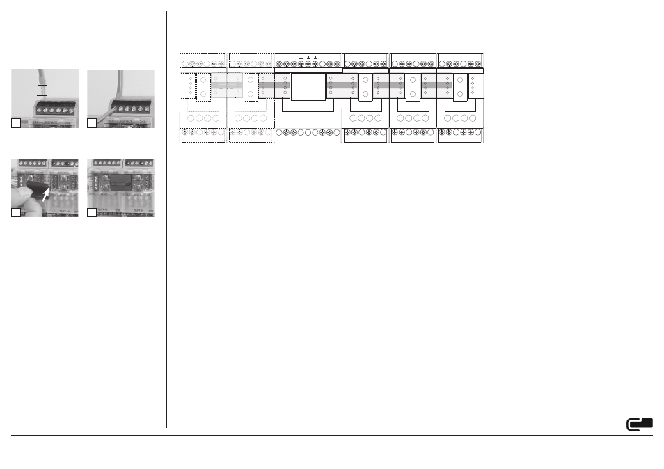
• The module can be aligned without interspace. Use the jumper
plug to connect bus and supply voltage when the modules are
mounted in series.
• The maximum quantity of modules connected in line is limited
to 15 or to a maximum power consumption of 2 Amps (AC or
DC) per connection to the power supply. For any similar block of
additional modules a separate connection to the power supply is
mandatory.
Preparing cable for connection.
Strip the wire by 7 mm, attach an end sleeveif necessary, insert
the wire into the contact and tighten the terminal screw with a
screwdriver.
2
3
4
7 mm
1
6. Mounting
Power down the equipment
Mount the module on standard rail (TH35 per IEC 60715 in
junction boxes and/or on distribution panels).
Installation
Electric installation and device termination shall be done by
qualified persons only, by respecting all applicable specifications
and regulations.
+24V
NG4
B+
A-
B+
A-
24 V
GND
L
24V
24V
24V
T
T
T
L
N
N
A-
B+
24V
24V
24V
24V
24V
24V
24V
24V
24V
24V
B+
B+
B+
B+
B+
A-
A-
A-
A-
A-
B+
B+
B+
B+
B+
A-
A-
A-
A-
A-
24 V
24 V
24 V
24 V
24 V
GND
GND
GND
GND
GND
24 V
24 V
24 V
24 V
24 V
GND
GND
GND
GND
GND
2+
2+
2+
2+
2+
2-
2-
2-
2-
2-
1+
1+
1+
1+
1+
1-
1-
1-
1-
1-
3+
3+
3+
3+
3+
3-
3-
3-
3-
3-
4+
4+
4+
4+
4+
4-
4-
4-
4-
4-
B+
A-
B+
A-
24 V
24 V
B+
B+
GND
GND
B+
B+
No 24 V DC transmission!
No 24 V DC transmission!
No 24 V DC transmission!
No 24 V DC transmission!
No 24 V DC transmission!
No 24 V DC transmission!
No 24 V DC transmission!
No 24 V DC transmission!
No 24 V DC transmission!
24 V DC output voltage
L / N operating voltage 110-240 V AC
7. Termination possibility
• Connection on the right side of the NG4 for voltage feeding and bus tap to the following bus modules (with jumper connection for example)
• Conneciton on the left side of the NG4 transfer of the bus connection by jumper connection. No 24 V DC connection!
• Parallel connection of several NG4 devices is not possible.