Installation, Canbus termination, Connector pin assignments – Contemporary Control Systems CANPCI User Manual
Page 4: Support files
TD020900-0IC
4
INSTALLATION
HARDWARE: The CANPCI can be installed in any PCI computer bus.
With power removed from the computer, remove its cover. Take care when
installing the CANPCI because both it and the exposed computer
motherboard are sensitive to electrostatic discharge. To prevent inadvertent
damage, touch the metal chassis of the internal power supply to discharge
yourself then remove the CANPCI from its protective ESD package.
CANbus Termination
If the CANPCI is located at the end of a trunk, line-matching
impedance is required. A 124-ohm resistor is supplied for this purpose
and is invoked by a jumper on header JP6. If the CANPCI is not
located at the end of a trunk,this jumper should be removed.
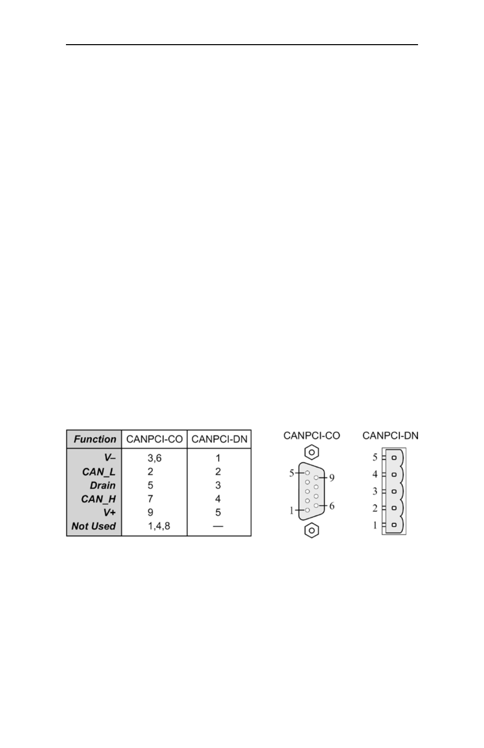
After termination is arranged, insert the CANPCI into an available PCI
bus slot. Once the CANPCI is mounted, it can be attached to the
CANbus. As illustrated below, the CANPCI-CO is provided with a DB-9
male connector for attaching to the CANbus, whereas he CANPCI-DN
uses an open style male connector with screw terminals. To facilitate use
of the screw terminals, a mating female connector has been provided.
Hardware installation is completed by replacing the computer cover.
CONNECTOR pIN ASSIGNmENTS
Support Files
In support of sustainable manufacturing and environmental legislation,
Contemporary Controls has refrained from providing a software disk or
CD with this product. A driver, API and utility program can be obtained
by contacting Contemporary Controls.