Installation, Hardware, Software – Contemporary Control Systems CANISA User Manual
Page 3
INSTALLATION
HARDWARE: The CANISA can be installed in any ISA computer bus.
With power removed from the computer, remove its cover. Take care when
installing the CANISA because both it and the exposed computer
motherboard are sensitive to electrostatic discharge. To prevent inadvertent
damage, touch the metal chassis of the internal power supply to discharge
yourself, then remove the CANISA from its protective ESD package.
Before proceeding with the installation, configure the jumpers according to
the instructions in the section entitled “Configuring Jumper Settings.”
After the jumpers are properly set, insert the CANISA into any available
ISA bus slot. Once the CANISA is mounted, it can be attached to the
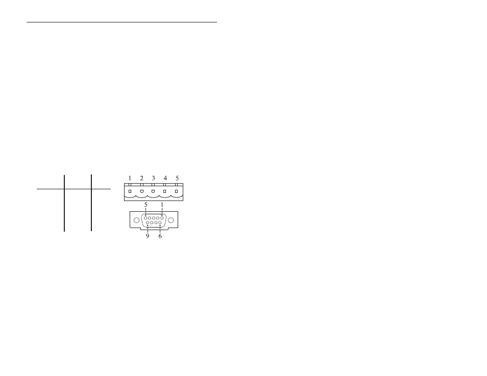
CANbus with either the screw terminals or the DB-9 connector. To
facilitate use of the screw terminals, a mating female connector has been
provided. The CANISA complies to the physical layer specification for
isolated ports, therefore bus power (V+, V-) must be present in order for its
transceiver to function. Hardware installation is completed by replacing the
computer’s cover.
Connector Pin Assignments
Function
V –
CAN_L
Drain
CAN_H
V +
Not Used
Screw
Terminal
DB-9
1
3,6
2
2
3
5
4
7
5
9
—
1,4,8
SOFTWARE: The CANISA comes with a disk which contains the driver
files which allows the operating system to allocate computer resources to the
card. The instructions for installing these files are provided on the disk in
the file named README.TXT.
TD990520-0I
E
3