Comtech EF Data LTT1450G User Manual
Page 22
Operation
LTT1450G Ku-Band Loop Test Translator
3-4
TM063 - Rev. 1
5
VTPR. Primary Loop Voltage
6
VT25 MHz Loop Voltage
7
Not Used
8
Not Used
9
Not Used
Correct voltage levels for the VTPRI loop should 1.5 to 7.8 volts, and 1 to 3.9 volts for the VTPRI loop.
3.3.5 User Serial Port (J6)
The user serial port is a DB 9-pin female connector at the rear of the translator. This port provides a
serial interface that can be configured as either an RS232, RS422 or RS485 interface. This port allows
the user to remotely control all of the features outlined in the Serial Protocol (Section 5). The serial port
comes configured as an RS-232 Serial port for DCE unless indicated otherwise. The pinout of the D-sub,
9-pin socket connector configured for RS232 or RS422 is as follows:
Operator Serial I/O Connector (Rear Panel)
J6 DB 9 Pin#
RS232 (Factory)
RS422
AS/1036 J6
1
N/C
RXData\
1
2
TXData
TXData
3
3
RXData
RXData
5
4
DTR----to pin 6
DTR---to pin 6
7
5
GND
Gnd
9
6
DSR----to pin 4
DSR ---to pin 4
2
7
RTS----to Pin 8
RTS----to Pin 8
4
8
CTS----to pin 7
CTS----to pin 7
6
9
N/C
TXData\
8
Note that in order to obtain these signals at the output connector, the jumper configuration on the
AS/1030 Controller PWB must have been performed as outlined in Appendix C. A summary of jumper
selections is as follows:
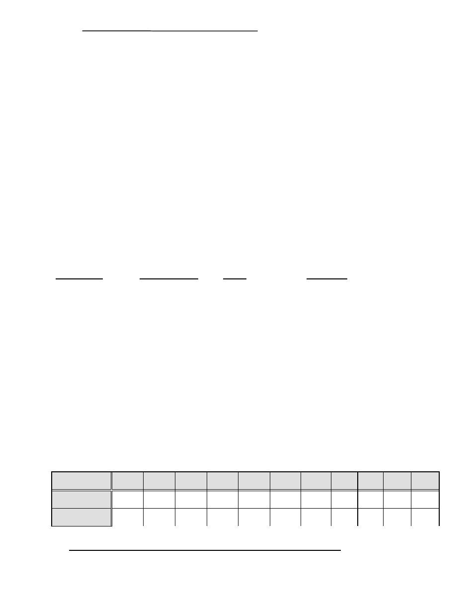
Configuration
JP1-1
JP1-2
JP1-3
JP1-4
JP1-5
JP1-6
JP8
JP4
JP7
JP5
JP6
RS232
OUT
OUT
OUT
OUT
IN
IN
OUT
OUT
IN
OUT
OUT
RS422
IN
IN
IN
IN
OUT
OUT
OUT*
OUT
OUT
OUT
IN