Comtech EF Data LTT1450G User Manual
Page 19
LTT1450G Ku-Band Loop Test Translator
Operation
TM063 - Rev. 1
Page 3-1
Section 3 - Operation
3.0
Operating Procedures
3.1
Operator Controls
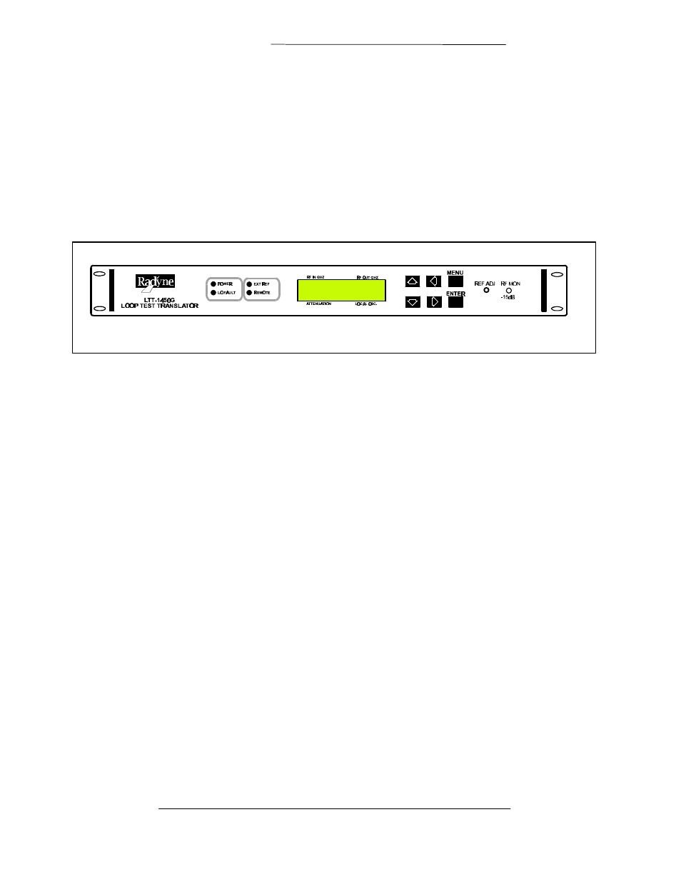
Figure 3-1 below shows the front panel elevation, controls and indicators of the LTT1450. Front panel
controls and indicators are as follows:
Figure 3-1. LTT1450G Front Panel Controls and Indicators
3.1.1 Power ON/OFF
The power on/off rocker switch allows front panel control of power to the translator. This switch controls
primary line voltage to the translator’s onboard power supply. By cycling the power switch to the
translator, the microcontroller will also reset.
3.1.2 Power LED
An illuminated POWER LED indicates that the LTT1450 onboard power supply is operating.
3.1.3 Freq Adj.
The front panel frequency adjustment control allows the operator to fine-tune the frequency of the
internal 5 MHz ovenized oscillator to within
±
5 x 10 E
-8
. This level of accuracy requires that the input
signal be synthesized and coherent with a frequency standard used in the frequency counter. Under
normal operation, adjustment of this oscillator will most likely not be required.
3.1.4 RCV Monitor
The receive monitor ports allow the operator to access a sample of the received signal (coupled by -15
dB) from the Ku-Band converter module.
3.1.5 EXT Reference LED
The EXT REF LED provides an indication to the operator that an external reference signal has been
detected on the REF IN connector located at the rear panel of the translator. An EXT REF indication and
no LO FAULT indication means that the translator has correctly synchronized the selected LO band with
the external 5 or 10 MHz signal. If an EXT REF indication is accompanied by a LO FAULT indication,
the operator should remove the external reference signal. If the LO fault clears, the translator was unable
to synchronize to the frequency of the external reference signal. The operator should test the frequency