Comtech EF Data LTT1450G User Manual
Page 11
LTT1450G Ku-Band Loop Test Translator
Description
TM063 - Rev. 1
Page 1-1
Section One - LTT1450G
Ku-Band Loopback Test Translator Description
1.0
Introduction
This manual is designed to serve as a guide during installation, operation, and interfacing of the Model
LTT1450G Ku-Band Loopback Test Translator. This manual describes operation of the microwave,
analog, and digital circuitry found in the translator. This dialogue is offered to provide insight into the
normal operation of the system as well as to provide assistance in identifying a faulty subsystem. The
level of description in this manual is not intended to provide information for component level test or
alignment. These functions are best performed by trained factory technicians.
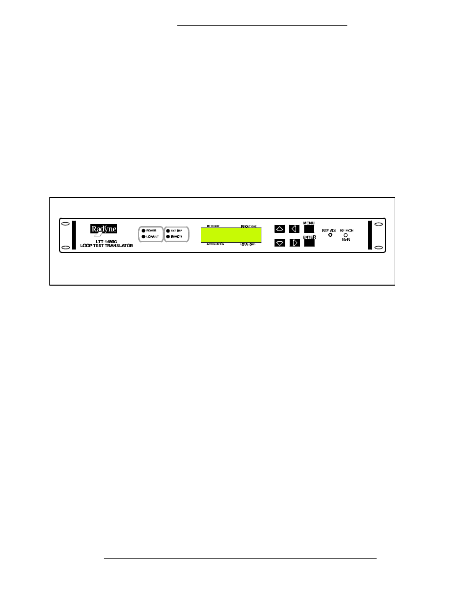
Figure 1-1. LTT1450G Front Panel
1.1
Model LTT1450G Ku-Band Translator Overview
The Model LTT1450G Global Ku-band Loopback Test Translator is designed to provide frequency
conversion of Ku-Band earth terminal uplink transmit carrier signals to earth terminal downlink receive
carrier signals for the purpose of testing all of the transmit and receive hardware simultaneously in the
earth terminal prior to acquiring actual satellite transponder space. Digital information to the MODEM
equipment will be received where it can be compared to that which was transmitted for the purpose of
determining a precise bit error rate. This function is normally provided by a bit error rate monitor (BER
Tester).
The LTT1450G translator is capable of converting Ku-Band uplink signals in the uplink 500 MHz band.
Uplink signals from either the output of the upconverter or HPA in the frequency range of 14.0 to 14.5
GHz are translated in four user-selectable 500 MHz bands covering the downlink frequency range of
10.95 to 12.70 GHz.
Output signal gain is variable in 0.1 dB increments via the front panel pushbuttons or serial remote
control. A PIN diode attenuator provides voltage controlled attenuation of the output signals in one dB
steps over the range of 00 to 60 dB. The serial port allows remote control of attenuation in precise 0.1dB
steps.
The local oscillator used in the translator is a four-band high-Q oscillator, phase locked to a 25 MHz
intermediate frequency crystal oscillator. The 25 MHz crystal oscillator is in turn locked to either an
internal 10.000 MHz ovenized SC-cut 3
rd
overtone crystal oscillator or to an external 5 or 10 MHz
external reference. The dual loop architecture used in the PLOs provide for a typical 14 dB
improvement over 20 Log N. In this way, the phase noise of the local oscillators is independent of the
phase noise of the internal or external 5 or 10 MHz references.