Codan Radio MT-4E Analog and P25 Digital - Maintenance Guide User Manual
Page 14
MAINTENANCE GUIDE | MT-4E ANALOG & P25 DIGITAL RADIO SYSTEMS
Chapter 2: Installation
Page 6
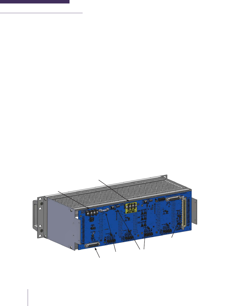
3. Connect the primary power (+10 Vdc to +17 Vdc, +13.8 Vdc nominal) to the Barrier Strip power input
on the rear of the subrack as shown in Figure 2-2. Ensure that the power source does not exceed +18
Vdc. Use a wire gauge suitable for delivering the power required by the subrack(s). If the subrack is
using a DC-DC or AC-DC Power Supply, refer to the specifi c manual supplied with the equipment for
installation instructions.
Reverse voltage protection and over voltage protection (transient suppressor) is provided at the main
power (+13.8 Vdc) input as well as the +9.5 Vdc line. The main power input is protected with a standard
fast-blow 15 amp fuse. These components may require replacing if the power supply is not connected
properly, or even after a power surge or a lightning strike. The two transient suppressors have different
voltage ratings for the main power input and +9.5 Vdc lines.
4. Install the System Regulator, Receiver, Transmitter, Power Amplifi er and Control Card modules in to
the subrack using the proper guide rail slots if not already done. When installing modules, ensure the
quick release fasteners on the top and the bottom of the modules are in the unlocked (slot should be
horizontal) position before insertion to the guide rails. To lock the quick release fasteners, push and
turn the fastener 90 degrees clockwise with a fl at screwdriver.
Note: MT-4E modules may be removed or inserted from the subrack while power is supplied without
damaging the equipment.
5. Interconnect +9.5 Vdc and +13.8 Vdc power between subrack units if one of the subracks does
not include a system regulator (no system regulator is required for a second subrack with only power
amplifi ers mounted in it). If a CI-RC-4M Multiple Link Controller is part of the system, connect the
+9.5 Vdc from the subrack to the controller. Connect the audio, channel select and control signal lines
from a CI-RC-4M Multile Link Controller to the optional screw-type A-PNL-AUX96-3 auxiliary terminal
connector or use the DB25 connector to connect the to a CI-RC-4M-G2 Multiple Link Controller.
Figure 2-2: Subrack Power Connections
Power Input
+10 to +17 Vdc
+13.8 Vdc Nominal
+9.5 Vdc Regulated
Power Input / Output
(used for interconnecting
2 subracks or powering
CI-RC-4M)
P1 Auxiliary
Connector
Fuse
Reverse and
Over Voltage
Protection
CI-RC-4M-G2
connector