Introduction - continued, Mounting - mechanical, Wiring – Cloud Electronics LE-1 User Manual
Page 2: Le-1 installation guide v1.0 2
LE-1 Installation Guide v1.0
2
Introduction - continued
Two types of input connector are provided: dual phono sockets for line level signals
with a nominal level of 0dBu), and a 3.5mm stereo jack socket for higher level signals
(approx. +8dB nominal), such as are found at the headphone output sockets of portable
audio devices. Gain trim adjustment (
±12dB) is available on the faceplate, and a red
“Peak” LED illuminates when an input signal exceeds nominal level. The gain should
be adjusted so that the LED illuminates briefly only on the loudest sections of audio
programme.
Mounting - mechanical
The Cloud LE-1 fits a standard dual-gang electrical back box. The back box used should
have a depth of at least 35mm (1.25”). Note that the LE-1 is made in various faceplate
sizes to suit standard electrical plate sizes in use in the UK, USA and Australia; ensure
you have the correct version for your territory.
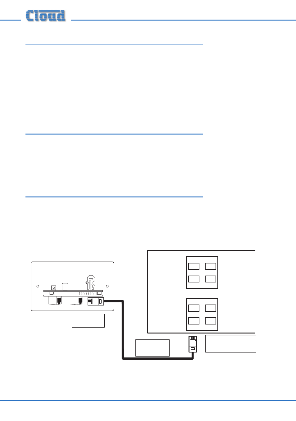
Wiring
The LE-1’s OUTPUT connector should be connected to one of the DCM-1’s
EXTENSION PORTs (Line inputs 1 to 4) with screened CAT-5 cable and shielded
RJ45 plugs. Do not connect any other equipment to the phono sockets of the same-
numbered Line Input on the DCM-1.
Connect to
Output socket
Screened
CAT-5 cable
LE-1
OUTPUT
LINK
Microphone Inputs
Extension Ports
DCM-1
1
2
3
4
1
2
3
4
Connect to an
unused Extension Port