Cdi-s200 serial control, Pinout, Port parameters – Cloud Electronics CDI-S200 User Manual
Page 8: Abridged command set, Cdi-s200 serial control pinout
CDI-S200 Installation Guide v1.0
8
CDI-S200 Serial Control
Pinout
The rear panel serial connector is a female
9-pin Dsub. The pinout is shown in the table:
PIN
FUNCTION
1
n/u
2
Data receive
3
Data transmit
4
DTR
5
0v
6
DSR
7
RTS
8
CTS
9
n/u
For many installations, it will only be necessary
to connect pins 2, 3 and 5. If the control
system’s serial port is also a 9-pin D-type, use
a D9-to-D9 “straight” cable (i.e., one wired
with pin 1 to pin 1, pin 2 to pin 2, etc.) If the
control system’s serial port is a screw-terminal
(or other type of) connector, the terminals will
most likely be marked “Tx”, “Rx” and “Gnd”,
or something similar. In this case, connect “Tx”
to pin 3 on the CDI-S200, “Rx” to Pin 2 and
“Gnd” to pin 5. See the following illustration
for details.
NOTE:
Not all control systems interpret
“Tx” and “Rx” the same way, and it may
be necessary for a “crossed” cable to be
used instead. A crossed cable is one with
pin 2 connected to pin 3 at the other end,
and vice-versa. If your CDI-S200 appears
to ignore control system instructions and
all connections, programming, etc., appear
satisfactory, try reversing pins 2 and 3 at one
end of the serial cable.
The installer should also check whether the
control system being used requires
RS-232C flow control (or “handshaking”) to
be implemented, and if so, whether hardware
control or software control is used. Hardware
handshaking (sometimes called RTS/CTS)
requires pins 7 and 8 to be connected.
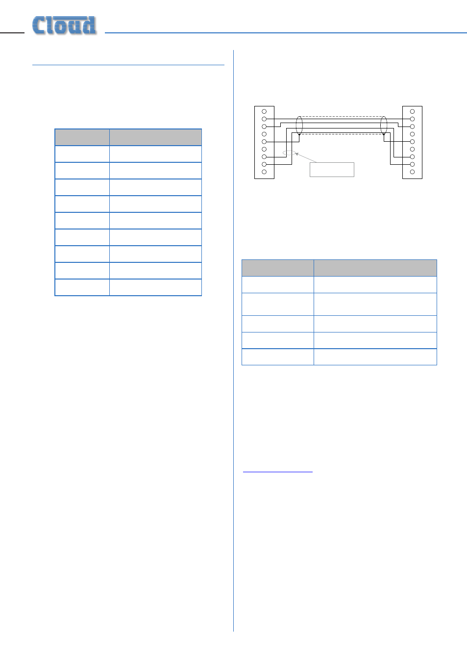
CONTROLLER
1
9
8
7
6
5
4
3
2
CDI-S200
TX
TX
RX
RX
CTS
CTS
RTS
RTS
Connect if hardware
flow control is required
“STRAIGHT” RS-232C SERIAL CABLE
Note that some installation require a “crossed” cable in this
case, pins 2 and 3 should be reversed at one end.
Port parameters
PARAMETER
VALUE/SETTING
Data type:
RS-232C serial
Data speed
300/1200/2400/4800/9600
baud, selectable by jumper
Word length
8 bits
Parity
None
Stop bits
One
Abridged command set
The commands listed in the General Format
table (page 9) are those most commonly
required. For all other commands, data
requests and responses, please refer to the
CDI-S200’s full RS-232C protocol document at
www.cloud.co.uk
.
The table provides the general format of each
type of command. The commands are given
in ASCII form; note that all characters in the
command, including the non-alphanumeric
ones, must be sent. The characters shown in
italics must be replaced by specific numeric
values when a command is sent.
Following the table, an example of each command
type is given; refer to the general format to see
how the variable characters are replaced by
specific values. The commands in the examples
are given in both ASCII and hex form.