Mechanical fitting and internal connection – Cloud Electronics CDI-S200 User Manual
Page 6
CDI-S200 Installation Guide v1.0
66
Mechanical fitting and internal
connection
If retrofitting the CDI-S200 to an existing
CX263 installation, turn the CX263 off,
remove its IEC mains lead and all other rear
panel connections (marking as necessary to
assist re-connection). If the CX263 is mounted
in a rack, remove it.
If fitting the CDI-S200 to a new CX263,
unpack the CX263.
In either case, place the CX263 on a flat
surface, with the rear of the unit facing you.
1. Undo the six screws securing the top
panel of the CX263; remove the panel.
Retain the screws.
2. Remove the blanking plate covering the
serial interface module connector hole in
the rear panel by removing the two self-
tapping screws securing it.
3. Identify the empty 16-pin header labelled
CON2 on the main PCB behind the
empty serial connector hole. Note there
is an M3 screw immediately behind this
connector, and another about 45 mm to
the right. Both these screws are clearly
marked with arrows; remove and retain
them.
CX263 PCB: CDI-S200 MOUNTING LOCATION
4. Screw the threaded ends of the two
25 mm mounting pillars supplied with the
CDI-S200 into the holes vacated by the
screws removed in Step 3.
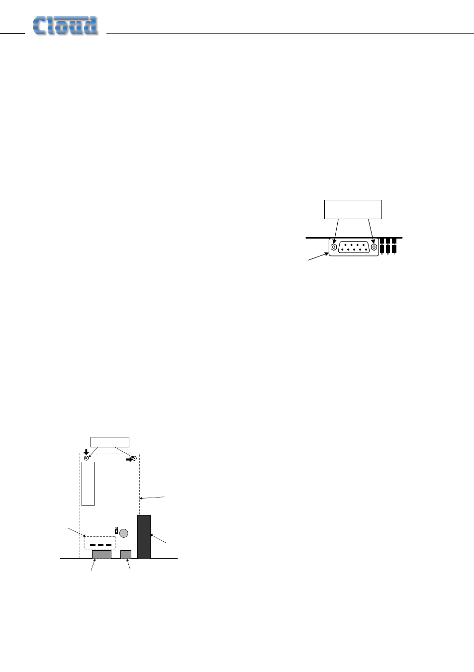
5. On the CDI-S200 board, remove the two
small threaded bushes on the D-type
connector; retain them. An M3 nut-driver
is the best tool for this. Note that these
bushes also retain the metal connector
shell – be careful to keep it in place during
the next two steps.
UNSCREW THESE
TWO BUSHES
RETAIN METAL SHELL
REAR VIEW OF CDI-S200 PCB
6. Plug the connector on the end of the
ribbon cable into connector CON2 on
the CX263 main PCB. Note it can only be
inserted one way round, with the cable
exiting to the left.
7. With the CDI-S200 PCB upside-down,
insert the D-type connector through the
hole in the rear panel. You will see that the
two holes at the other end of the PCB are
aligned with the mounting pillars fitted in
Step 4. Fix the board to the pillars using
the screws removed in Step 3.
8. Replace the two bushes removed in Step
5 adjacent to the D-type connector by
screwing them through the rear panel. The
two self-tapping screws removed in Step 2
are no longer required.