Cloud Electronics CDI-S200 User Manual
Page 7
CDI-S200 Installation Guide v1.0
7
CX263 switch settings
After the CDI-S200 card has been fitted, and
J4 – J6 and J19 – J24 (on the CX263 main
PCB) set as described above, the top cover of
the CX263 can be replaced, using the original
screws.
The three blue rear panel switches
DIG/
AN
(adjacent to the
RSL-6
connectors)
should now be set to
DIG
– i.e., in their ‘out’
position. The three blue rear panel switches
FR/REM
(next to them) should be set to
REM
– i.e. in their ‘in’ position. The CX263 is
now ready for full serial remote control.
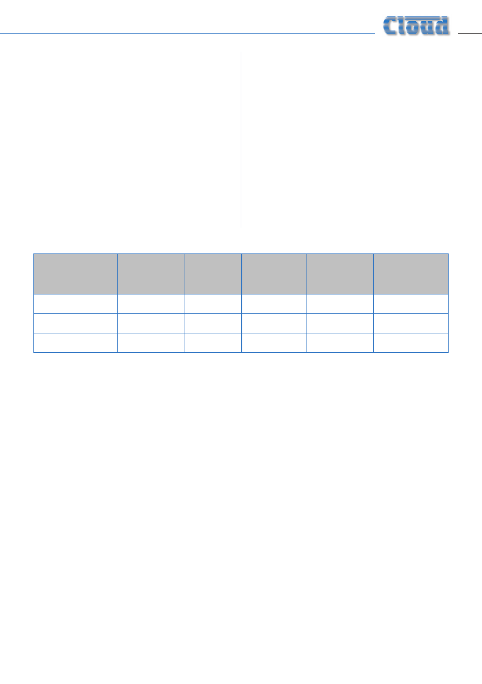
Partial music function control
It is also possible to configure the CX263
so that the CDI-S200 only controls certain
unit functions, leaving others to be manually
controlled, either from the front panel or from
a Cloud RSL-6 remote control plate. If this is
required, set the rear panel switches and the
internal jumpers J19 to J24 according to the
table below.
MUSIC
SOURCE
MUSIC
LEVEL
DIG/AN
switch
FR/REM
switch
Jumpers
J19, J21, J23
Jumpers
J20, J22, J24
CDI-S200
CDI-S200
DIG
REM
*
SW
CDI-S200
RSL-6/RL-1
AN
REM
DG
SW
Front panel
CDI-S200
DIG
REM
*
FR
* When the CDI-S200 is to control music level, jumpers J19, J21 and J23 may be set in either the DG or SW position.
However, they must NOT be removed altogether.