3 schematic diagram 4 installation, 5 stereo inputs, 1 sensitivity and gain control – Cloud Electronics CX263 User Manual
Page 8: Zones 1-3
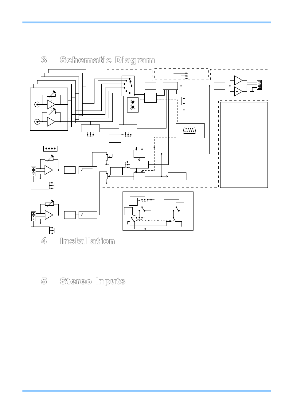
3 Schematic Diagram
4 Installation
The Cloud CX263 occupies one unit of standard 19” equipment rack. The microphone inputs and all zone
outputs are balanced. Ventilation holes on the base of the unit should not be obscured. The CX263 is
150mm deep but a depth of 250mm should be allowed to clear connectors.
5 Stereo Inputs
The line inputs are suitable for most music sources such as compact disc players, tape players and
receivers etc.. All inputs are unbalanced and use RCA type phono sockets. Input impedance is 48k
Ω
.
5.1 Sensitivity and Gain Control
All six line inputs have pre-set gain controls which are accessible on the rear panel, adjacent
to their respective input sockets. The input sensitivity can be varied from -18dBu (100mVrms)
to + 6dBu (1.5Vrms). The pre-set gain controls should be set so that all the input signals
operate at the same level (0dBu) within the CX263, which ensures that the music level controls
have an optimum control range.
CX263 Zone Mixer
Installation and Setup Guide
CLOUD ELECTRONICS LIMITED
2
V2 100904
LINE 6
LINE 5
LINE 4
LINE 3
LINE 2
LINE 1
L
R
1
1
1
2
2
2
3
3
3
EQ
GATE
GATE
PRIORITY
PRIORITY
RELEASE
TIME
PHANTOM
PHANTOM
LINE 6
PRIORITY
EQ
EQ
VCA
SPEAKER
MODULE
OPTIONAL
REMOTE
(RSL-6)
MIC 1 ACCESS CONTACTS
MIC 1 INPUT
MIC 2 INPUT
GAIN
GAIN
100Hz
100Hz
+
GAIN
AVO
OFF
OFF
MONO
3s
NO JUMPER=12s
ACC
ON
ON
STEREO
6s
OFF
ON
FROM
OTHER
CHANNEL
MUSIC
MUTE
ADDITIONAL JUMPERS
J4-6:
J7:
J12-15:
J20, 22, 24:
J19, 21, 23:
BYPASS MIC 1 ACCESS FOR
ZONES 1-3 RESPECTIVELY
NORMALLY OPEN/CLOSED
MUSIC MUTE CONTACT SELECT
BYPASS EQ CARD
FITTINGS FOR INDIVIDUAL OUTPUT
J12:
ZONE 1 R
J13:
ZONE 1 L
J14:
ZONE 2
J15:
ZONE 3
FORCE FRONT PANEL
SOURCE SELECTION
J20:
ZONE 1
J22:
ZONE 2
J24:
ZONE 3
FORCE CDI-S200
SOURCE SELECTION WHEN
REMOTE.
J19:
ZONE 1
J21:
ZONE 2
J23:
ZONE 3
J3
J8: ZONE 2
J9: ZONE 3
J10: ZONE 1
J16: ZONE 3
J17: ZONE 2
J18: ZONE 1
J1
J2
J11
ZONES 1-3
OPTIONAL
SERIAL INTERFACE
ZONE1
ONL
Y
SEE
DETAIL
A
DETAIL A
SRC
RSL6
CDI-S200
FRONT
PANEL
VCA
J19: Z1
J21: Z2
J23: Z3
J20: Z1
J22: Z2
J24: Z3