2 bose® active equalisation modules – Cloud Electronics CX263 User Manual
Page 17
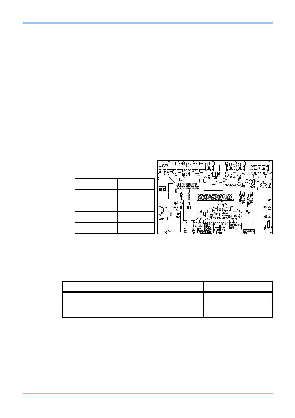
9.2 Bose® Active Equalisation Modules
Each output channel has the facility to connect a plug-in Bose® equaliser module.
See the table below for details of the connector for each output and the respective bypass
jumper.
Installation:
1.
Switch off the mains supply and remove the CX263’s power lead.
2.
Remove the unit’s top panel
3.
Remove bypass jumper (see table below for jumper map). We advise that when
removing a jumper link, the connector remain attached to one pin of the header.
This prevents loss of the link.
4.
Fit the Bose® EQ module card to the connector. The EQ card should be
perpendicular to the main board.
5.
Apply moderate pressure to the Bose® EQ module until it locates with a click.
6.
Replace the top panel.
Current Consumption:
The CX263 can provide 80mA of power to internal modules. If this limit is exceeded, the unit
will eventually overheat and then shutdown. Below is a table detailing the types of equalisation
module available and their relative current consumption.
CX263 Zone Mixer
Installation and Setup Guide
CLOUD ELECTRONICS LIMITED
11
V2 100904
OUTPUT
JUMPER
ZONE 1 RIGHT
J12
ZONE 1 LEFT
J13
ZONE 2
J14
ZONE 3
J15
EQ Module Bypass Jumpers
Current Consumption of Active Equalisation Modules by Model
Location of Jumpers J12-15
MODEL OF EQUALISATION MODULE
CURRENT REQUIRED
M8, M32, MA12, 402, 502A, 802, MB4, MB24, 502B, 502BEX
12mA
LT3302, LT4402, LT9402, LT9702
17mA
M16
24mA