Tips for the service technician, Gas equipment assembly – Dometic RM2652 User Manual
Page 12
12
SECTION D. MAINTENANCE & SERVICE
Tips for the Service Technician
The user should be aware of service that must be done on a regular schedule to keep the refrigerator operating properly.
The service should only be performed by a qualified technician who is familiar with LP gas systems and refrigerators.
1. REFRIGERATOR REMOVAL
Before working on the refrigerator, make sure the AC voltage
and DC voltage leads are disconnected. Shut off the gas
supply at the LP tank. Disconnect the gas supply line. Cap
the gas supply line, loosen the screws anchoring the
refrigerator to the enclosure and slide the refrigerator out of
the compartment.
Replacement is the reverse of removal. Check all connec-
tions for gas leaks. Refer to
Section A, Item 1 to 12 of
Installation Instructions.
2. PERIODIC MAINTENANCE
To keep your Dometic refrigerator operating efficiently and
safely, periodic inspection and cleaning of several compo-
nents once or twice a year is recommended.
A. It is important to keep the area at the back of the
refrigerator clean. Check the lower vent, upper vent and
area between these openings for any obstructions such
as bird/insect nests, spider webs, etc. Clean the coils on
the back of the refrigerator. Use a soft bristled brush to
dust off the coils.
It is important to keep the refrigerator vent area free from
combustible material, gasoline and other flammable
vapors or liquids.
NOTE: The following maintenance is required once or twice
a year, but should only be done by a qualified serviceman
who is familiar with LP gas systems and refrigerators.
B. Check all connections in the LP gas system (at the back
of the refrigerator) for gas leaks. The LP gas supply must
be turned on. Apply a noncorrosive bubble solution to all
LP gas connections. The appearance of bubbles indi-
cates a leak and should be repaired immediately by a
QUALIFIED SERVICEMAN WHO IS FAMILIAR WITH
LP GAS SYSTEMS AND REFRIGERATORS.
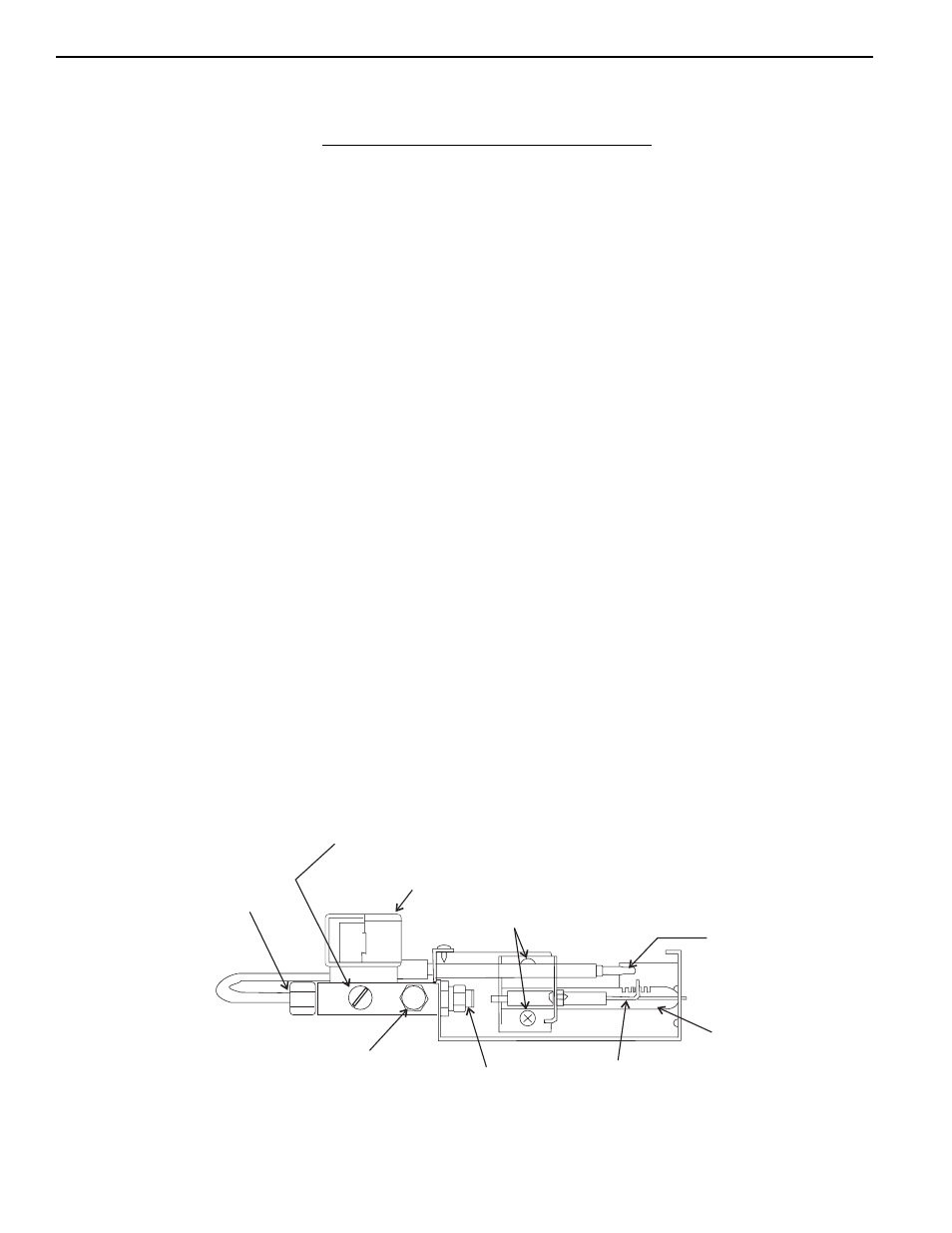
GAS EQUIPMENT ASSEMBLY
FIG. 12
MANUAL SHUTOFF VALVE
Use a quarter dollar or a slotted screwdriver
to change position
SOLENOID VALVE
BURNER MOUNTING SCREWS
THERMOCOUPLE
BURNER
TUBE
SPARK
ELECTRODE
BURNER
JET
PRESSURE TEST
PORT
INLET FITTING