Installation, Continued – Desa CDCFPRA User Manual
Page 14
www.desatech.com
116658-01C
14
iNsTallaTioN
Continued
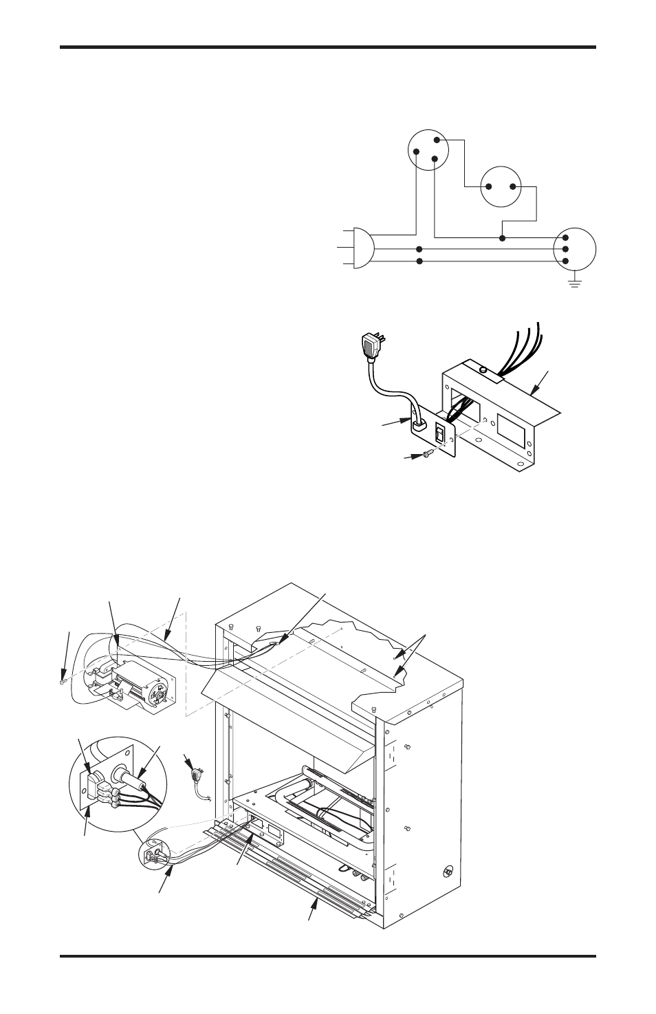
5. In top of the fireplace cabinet, locate the four
mounting holes on the outer casing. Align
these four holes with those on the blower
bracket assembly. Attach blower bracket as-
sembly to the outer casing with 4 #10 screws
provided (see Figure 16).
6. Route the wire harness through the hole in left
side of baffle and between firebox wrapper and
outer casing.
7. Insert the 4 wire harnesses from behind the
remote/blower bracket through hole in rear
of bracket with bushing and through the left
rectangular hole to front of fireplace (see
Figure 16).
8. Reconnect red wire to switch position 3.
Reconnect blue wire to switch position 1.
Reconnect green and white wires.
9. Install the switch plate on the remote/blower
bracket with 2 #10 screws provided (see Figure
18). Route power cord out of the cabinet by
inserting it through the bushing on the outer
casing (see Figure 16). Plug fan kit into 120-
Volt grounded power supply and test operation.
Note:
When switch is in the AUTO position,
the fan will start after the fireplace has run for a
few moments. The fan will continue to run for
several moments after the fireplace has been
turned off. When switch is in the ON position,
the fan will run until turned to OFF.
3
2
1
O
F
F
P
ILO
T
O
N
H
I
L
O
Figure 16 - Installing Blower Bracket Assembly (Remote-Ready Unit Shown)
Wire Harness
Blower Bracket
Assembly
Screw
Wire Harness
Switch
Wiring Routing
Hole in Baffle
Switch Plate
Remote/
Blower
Bracket
Power
Cord
Lower Louver Door
Blower
Mounting
Holes
Figure 18 - Installing Switch Plate to
Remote/Blower Bracket
Figure 17 - Wiring Diagram For Blower
Accessory Standard Installation
Red
Red
Fan Switch
(Auto/Off/On)
Blue
Blue
Thermostat
Switch
(N.O.)
Green
White
Green
White
On
110/115
V.A.C.
Blower
Motor
Black
Off
1
2
3
Auto
Remote/
Blower
Bracket
Switch
Plate
Screw
10. Reinstall upper louver beginning with bottom
screws (see Figure 15, page 13). Close lower
louver door.