Installation – Desa CDCFPRA User Manual
Page 13
www.desatech.com
116658-01C
13
iNsTallaTioN
Continued
12. Lower bottom louver door. Use 3" wood
screws provided with mantel accessory to at-
tach fireplace to base (see mantel instruction
sheet).
Figure 14 - Assembling Brass Trim
Side Brass
Trim
Top Brass
Trim
Mitered Edge
Shim
Set Screws
Adjusting
Plate
Slot
INSTALLING OPTIONAL bLOWeR
ACCeSSORy GA3450TA
Removing Upper Louver
To install the blower accessory, you must first
remove the upper louver.
1. Lift screen off fireplace and remove log set if
installed.
2. Remove 4 screws from upper louver (see
Figure 15). Save these screws.
3. Pull upper louver straight out from the cabinet. Be
careful not to scratch the paint. Set louver aside.
4. Open lower louver door by swinging door
down (see Figure 15).
Assembling Perimeter Trim (Perimeter
trim shipped with mantel)
1. Remove packaging from three remaining
pieces of trim.
2. Locate two adjusting plates with set screws,
and two shims in the hardware packet.
3. Align shim under adjusting plate as shown in
Figure 14.
4. Slide one end of adjusting plate/shim in slot on
mitered edge of top brass trim (see Figure 14).
5. Slide other end of adjusting plate/shim in slot
on mitered edge of side perimeter trim (see
Figure 14).
6. While firmly holding edges of perimeter trim
together, tighten both set screws on the adjust-
ing plate with slotted screwdriver.
7. Repeat steps 1 through 6 for other corner.
8. Set perimeter trim assembly aside for later
installation.
Installing blower Accessory
CAUTION: Label all wires
prior to disconnection when
servicing controls. Wiring errors
can cause improper and danger-
ous operation.
CAUTION: Verify proper op-
eration after servicing.
Note:
If you are using a mantel with your fireplace,
use the following instructions. If your fireplace is
built-in, see For Built-In Installation, page 15.
1. Install snap bushings found in blower kit into
hole in left side of outer casing and into one of
the holes in rear of remote/blower bracket.
2. Make sure the wire harness is firmly connected to
the terminals on the blower bracket assembly.
3. Note the wire locations on back of AUTO/
OFF/ON switch. The terminals on back of
switch are numbered 1, 2, and 3. Carefully
remove red wire from terminal 3 and blue wire
from terminal 1. Black wire can remain on
middle terminal 2 (see Figure 16, page 14).
4. Carefully disconnect green and white wires at their
insulated connectors (see Figure 16, page 14).
O
F
F
P
ILO
T
O
N
H
I
L
O
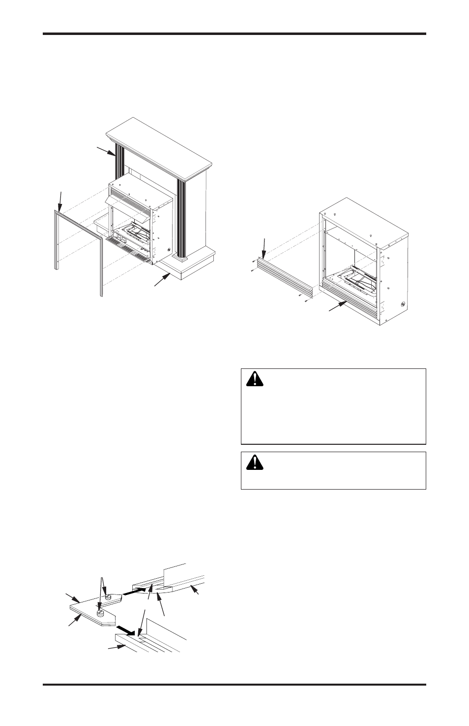
Figure 13 - Installing Fireplace into
Mantel Assembly
Figure 15 - Removing Top Louver and
Opening Bottom Louver
Cabinet
Mantel
Assembled
Trim
Hearth Base
Top
Louver
Bottom Louver