Operating instructions / control box, Operating instructions – BUG-O Systems Stiffener Welder User Manual
Page 8
8
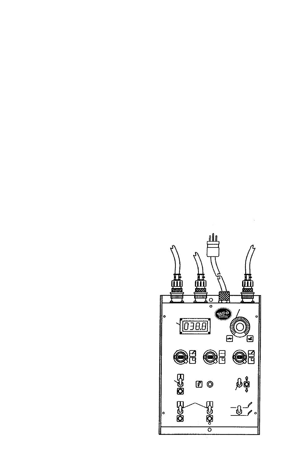
1. Connect the power sources, to the LN-9F wire feeders. (Refer to the LN-9F manual).
• Power for the BUG-O drive (120 VAC, 50/60, 1 PH) is taken from the “right” LN-9F control
box via a line connector. Therefore, the “right” power source control cable must be
connected and the power source turned “ON” to provide power to the BUG-O Control
Box.
2. Turn the lower trigger interlock toggle switch on both LN-9F’s to the “OFF” position.
• Make sure
Wire Feed Switches (B) are “OFF”.
3. Turn the power source “ON” and feed the wire from the reels to the torches as follows:
• Place
“Forward-Off-Reverse” Switch (D) on BUG-O Control Box in the center “OFF”
position.
• Turn the
“Power Switch” (A) “ON”.
• Place wire in feed rolls and “inch” wire by “jogging” the wire feed toggle switch on the
LN-9F until the wire emerges at the tip of the torch.
• Position the torch tip and adjust the height for proper stick-out.
4. Set the welding travel speed: Put carriage Travel Direction Switch (D) in the center “OFF”
position and
Skip/Continuous Selector Switch (C) to “CONTINUOUS”. Speed is adjusted
with the
Carriage Speed Control (J), and the speed will display in the Digital Readout (H)
in inches per minute.
5. Select “Skip” or “Continuous” position on the Toggle Switch (C). If “Skip” is selected:
• Set
Skip Length (F) - Turn digital potentiometer clockwise to increase length. Push the
lever downward to lock setting.
• Set
Weld Length (G) - Turn digital potentiometer clockwise to increase length. Push the
lever downward to lock setting.
Note: The weld length depends on the weld speed and
time; and since this control actually sets the weld time, it has to be readjusted if the weld
speed is changed.
OPERATING INSTRUCTIONS
6. Set Crater Fill Time (E): Turn the digital
potentiometer clockwise to increase time (usually
crater fill time is very short). Push the lever
downward to lock setting.
7. Select travel direction: For welding, set the travel
direction switch “UP” so that the “rear” end (with
wire reels) is moving away from the starting
position.
8. Engage the Drive Wheel (see page 4).
9. Operate the unit to test the settings.
10. When ready to start welding:
• Set the voltage and wire speed on LN- 9F’s
by referring to the operation and instruction
manuals provided with the feeders.
• Turn both wire feed switches on the BUG-O
Control Box to “ON” (up).
• Set the travel direction switch to “FORWARD”
(up).
• Set either Skip or Continuous mode.
• Turn the power switch “ON” (up) to start
welding and travel.
TO
LEFT
WIRE
FEEDER
TO
RIGHT
WIRE
FEEDER
TO
DRIVE
UNIT
POWER CORD
CARRIAGE
SPEED
TRAVEL
SPEED
CRATER
LENGTH
SKIP
LENGTH
WELD
LENGTH
FWD
OFF
REV
POWER
INDICATOR
LIGHT
POWER
SWITCH
WIRE
FEED
CARRIAGE
TRAVEL
SKIP
CONTINUOUS
ON
OFF
B
C
D
A
E
F
G
J
H