11 ............auxiliary modes, Auxiliary modes chart – BUG-O Systems Programmable Shape Machine User Manual
Page 11
11
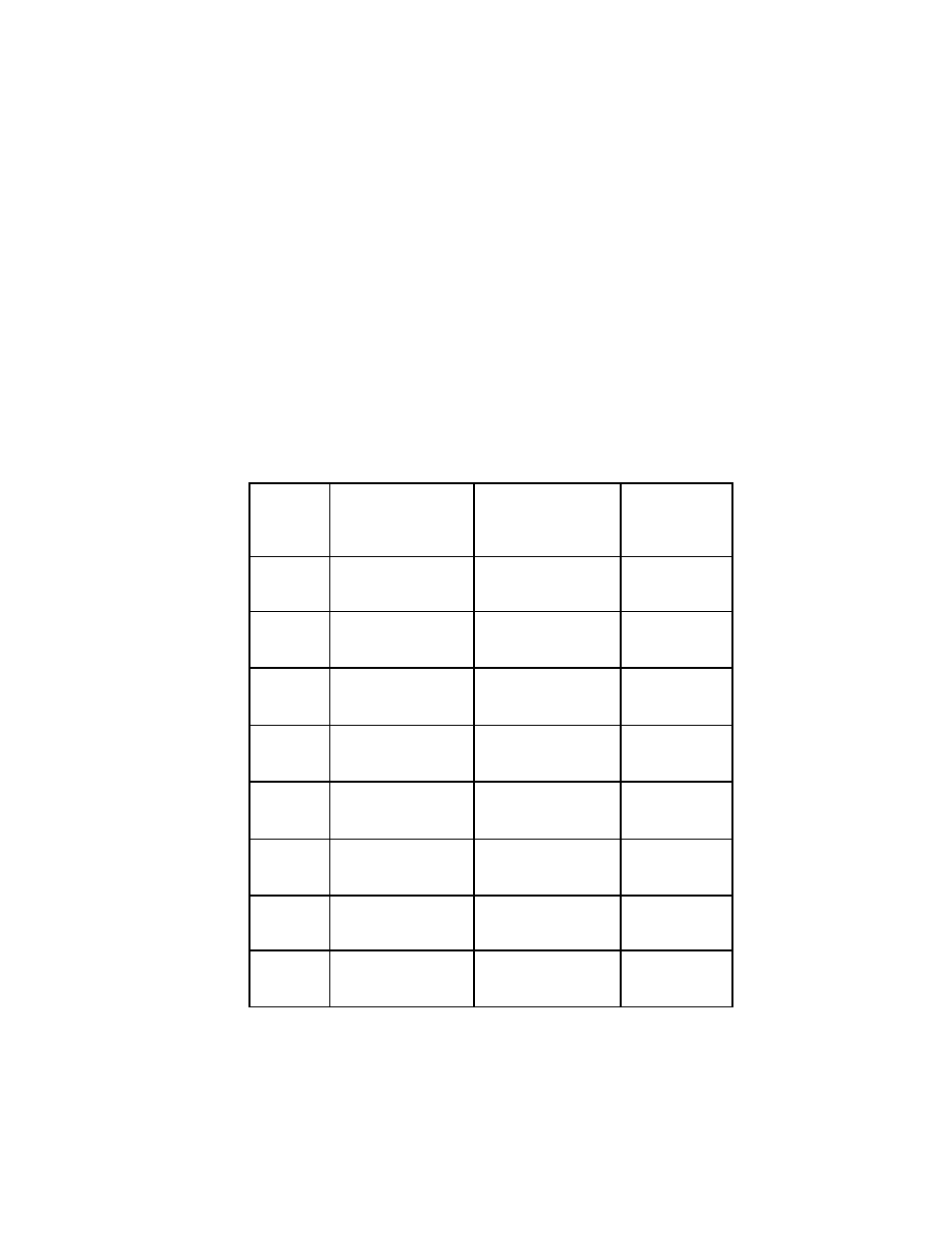
aUXILIaRY MOdES: TYPE 6, QUadRaNT 3
Mode
No.
Output 1
Output 2
Speed
0
Off
Off
Set
1
Off
On
Set
2
Off
Off
Hi
3
Off
On
Hi
4
On
Off
Set
5
On
On
Set
6
On
Off
Hi
7
On
On
Hi
This function allows the 2 internal Solid State Relay outputs to be independently turned ON and OFF, providing
control of 2 output signals; and also to switch the machine between Rapid Traverse mode and Set Speed.
The machine is shipped with OUTPUT (1) wired to the amphenol connector for the external relay or solenoid,
using pins A and C. By default, this Output turns ON when the START button is pressed to run a shape, and turns
OFF at the end of the shape. Both the contact relay and cutting solenoid use only Output (1).
OUTPUT (2) is present across pins A and D on the amphenol connector, but is not used by the standard relay
box - a custom box has to be made to use this output. By default the output is OFF when a shape is started, until
specifically turned ON by the Solenoid/Weld ON command Type 5, Quad 1.
Subsequently while running, the Type 5 ON and OFF commands turn both OUTPUTS On and Off together, and
both turn Off at the end.
When programming Type 6 Quad 3, a Mode Number is required to be entered. The 8 auxiliary modes, numbered
0 through 7, allow the setting of a mode with any combination of Outputs On or Off, and choice of Set Speed by
the speed knob, or maximum speed regardless of setting. The combinations are listed in the table below:
aUXILIaRY MOdES CHaRT
Chart #3