BSS Audio FCS-966 Owner's Manual User Manual
Page 22
For this, two other pieces
of equipment are required:
a pink noise source, and
an acoustic real time
analyser (RTA).
With the FCS 966
interposed between the mixer and amplifiers, with all sliders set to ‘zero’,
apply pink noise to the system at a level similar to that expected during normal
operation. Observe that the RTA has a number of bars or a line that indicates
the sound level in different parts of the spectrum. Adjust the FCS 966 so that
the RTA indicates as flat a response as possible. If you are lucky, the RTA will
have frequency bands marked the same as the FCS 966.
This is one of the major
uses for graphic equalizers
in sound reinforcement
applications. The FCS
966 would usually be
connected either to the
mixer ‘mix insert’ points,
or between the output of
the mixer and the input of
the amplifier or crossover.
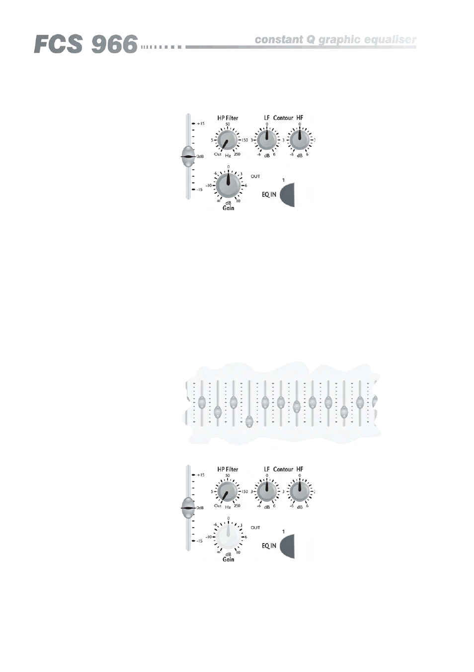
Set all frequency bands
to ‘zero’. With the room quiet and the offending microphone active, increase
the system gain slowly (the FCS 966 gain control is convenient for this) until
the system starts to howl. Be prepared to back off the gain quickly to stop this
getting out of hand. Carefully set the gain such that the system is gently feeding
back. Find the frequency band that corresponds to the tone that you are
hearing, and move this slider fully down; the feedback should stop. Increase
the system level and feedback will return, find the next offending frequency
band and again reduce it, this time though only half way. Repeat this again,
reducing the slider again to the half cut position. Increase the gain once
more, on this occasion though only reduce the band by 25%. The graphic
should now look something like figure 8.1. With four bands adjusted, there is
probably not much merit in continuing, as the sound will start to be adversely
affected.
8.2 Feedback
reduction
Application examples
Fig 8.1 using the graphic for
feedback reduction
8.3 Room equalisation