7 troubleshooting, 1 general, 2 troubleshooting summary general – Bronkhorst LIQUI-FLOW L30 User Manual
Page 20
BRONKHORST HIGH-TECH B.V.
page 20
9.17.044
7 TROUBLESHOOTING
7.1 General
For a correct analysis of the proper operation of a LIQUI-FLOW L30 meter or controller it is recommended to
remove the unit from the process line and check it without applying fluid supply pressure. In case the unit is
dirty, this can be ascertained immediately by loosening the compression type couplings and, if applicable the
flange on the inlet side.
Furthermore remove the cover and check if all connectors are fixed properly. Energising or de-energising of
the instrument indicates whether there is an electronic failure. When powering up the red LED is on and the
green LED is flashing for a second or two. Then the instrument should go in normal operation mode. See
document number 9.17.023 for detailed description of the LED indication.
After that, fluid pressure is to be applied in order to check behaviour.
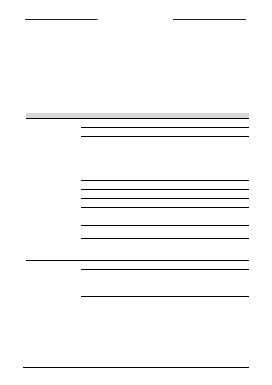
7.2 Troubleshooting summary general
Symptom
Possible cause
Action
No output signal
No power supply
1a) check power supply
1b) check cable connection
Output stage blown-up due to long lasting
shortage and/or high-voltage peaks
1c) return to factory
Supply pressure too low, or differential pressure
across meter too low
1d) increase supply pressure
Valve blocked/contaminated
1e) connect 0 .. 15 Vdc to valve and slowly
increase voltage while supply pressure is ‘on’.
The valve should open at 7V
3V; if not open,
then clean parts and adjust valve (qualified
personnel only)
Screen in inlet fitting blocked
1f) clean screen
Sensor failure
1g) return to factory
Maximum output signal
Output stage blown-up
2a) return to factory
Sensor failure
2b) return to factory
Output signal much lower than
setpoint signal or desired flow
Screen blocked/contamined
3a) clean screen
sensor blocked/contaminated
3b) clean sensor with a gas or fluid
Valve blocked/contaminated
3c) clean valve
Valve internal damage (swollen seat in plunger)
3d) replace plunger assembly and adjust valve
or return
Incorrect type of gas is used and/or pressure/diff.
pressure is to low
3e) try instrument on conditions for which it was
designed
Flow is gradually decreasing
Valve adjustment has changed
4a) see ‘1e’
Oscillation
Supply pressure/diff. pressure too high
5a) lower pressure
Controller adjustment wrong
5b) adjust controller
Software like FLOWPLOT can be used to do
this. Please contact the distributor for details.
Pipeline too short between pressure regulator
and LIQUI-FLOW
5c) increase length or diameter of piping
upstream
Valve sleeve or internals damaged
5d) replace damaged parts and adjust valve,
see ‘1e’ or return to factory
Small flow at zero setpoint
Valve leaks due to damaged plunger or dirt in
orifice
6a) clean orifice and/or, when replacing plunger
assembly, see ‘1e’
Pressure too high or much too low
6b) apply correct pressure
High flow at zero setpoint
Damaged diaphragm (only applicable to valves
with membrane)
7a) replace membrane seal
Disturbances in the flow
Gas in the system
8a) Purge the system
Expansion of liquids to gasses
8b) Check properties fluid used
Calibration error
Gas in the system
9a) Purge the system
Measure time to short
9b) Measure long enough to get a reliable
measurement
Right reference instrument
9c) The LIQUI-FLOW is a mass-flow
meter/controller and should not be checked with
a volume-meter.
Note: For other (more specific) problems see also troubleshooting parts in other documents.