13 electromagnetic compatibility, Conditions for compliance with emc requirements, 14 electro static discharge – Bronkhorst LIQUI-FLOW L30 User Manual
Page 12
BRONKHORST HIGH-TECH B.V.
page 12
9.17.044
2.13 Electromagnetic compatibility
Conditions for compliance with EMC requirements
All instruments described in this manual carry the CE-mark.
Therefore they have to comply with the EMC requirements, as they are valid for these instruments.
However compliance with the EMC requirements is not possible without the use of proper cables and
connector/gland assemblies.
For good results Bronkhorst High-Tech B.V. can provide standard cables. Otherwise follow the guidelines as
stated below.
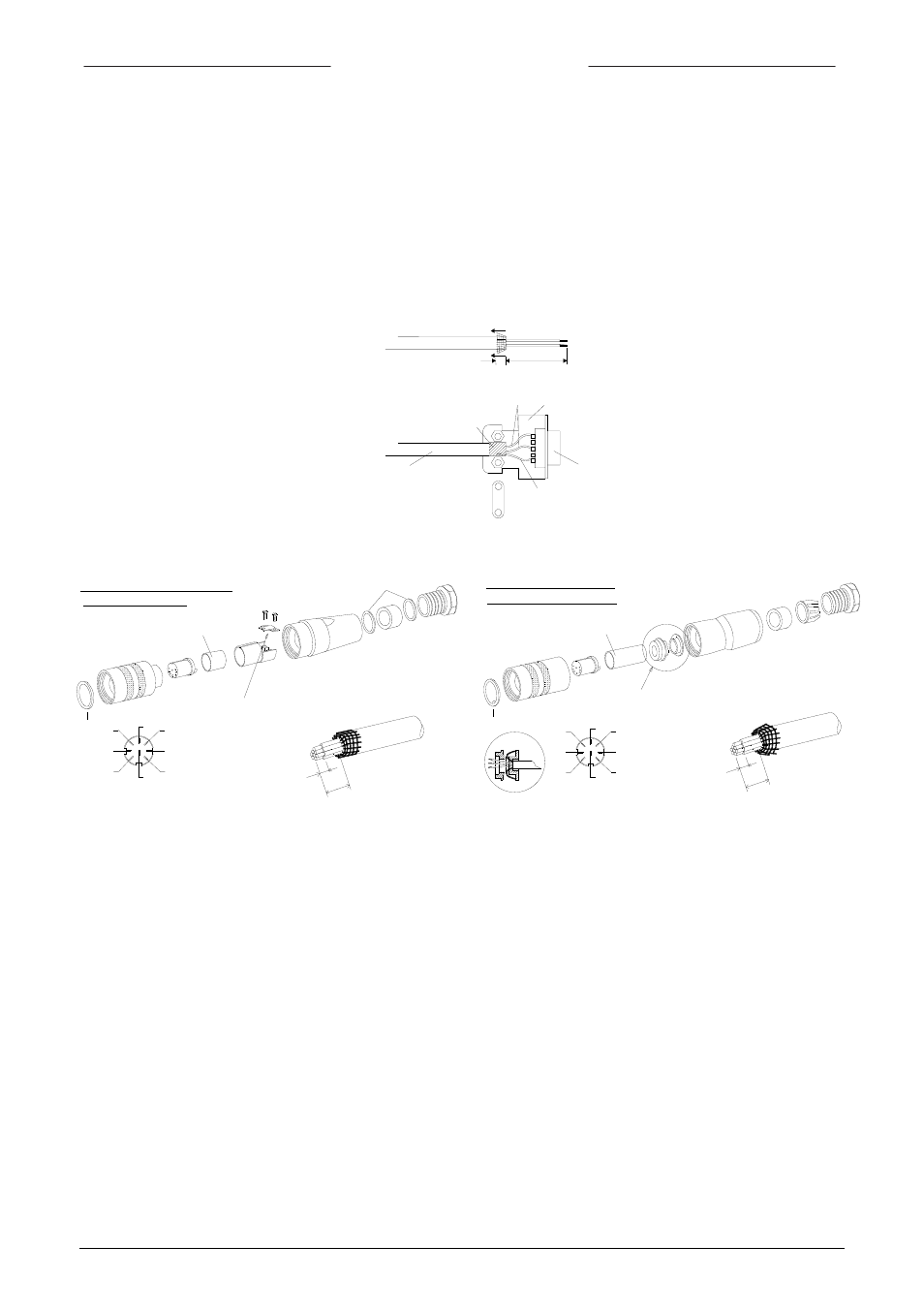
1. D-Connector assembly
2. Connector LIQUI-FLOW
Note:
When connecting the system to other devices (e.g. to PLC), be sure that the integrity of the shielding is not
affected. Do not use unshielded wire terminals.
1. For FLOW-BUS S(F)TP data (patch) cable connection to M12 connectors follow the instructions of the
supplier. It is important to use shielded twisted pair cables and shielded RJ45 modular jack connectors.
2. For PROFIBUS-DP, Modbus or DeviceNet data cable connections follow the instructions of the cable
suppliers for the specific field-bus system.
2.14 Electro static discharge
This instrument contains electronic components that are susceptible to damage by static electric discharges.
Proper handling procedures must be taken during installation, removing and connecting the electronics.
Fold the shield of the cable back over the cable (the shield must be around the cable).
Wind a copper tape around the shield.
Solder a black wire on the tape
and connect to pin 9 of connector
20 mm
8 mm
D-connector housing
metalized
connector
other wires
black wire
(shield)
copper tape
shielded cable
e.g. LAPP LiYCY
SHRINK SOLDERCONTACTS WITH SHRINKTUBING
BRE 160 BLACK OR EQ.
8 DIN CONNECTOR AMPHENOL
TRANSPARANT TUBING
C091 31D008 200 2
O-RING
CONNECTED TO THE CONNECTORHOUSING
FOLD THE SHIELD OF THE CABLE BACK OVER
THE CABLE.(THE SHIELD MUST BE AROUND
THE CABLE)
SHIELD OF THE CABLE SHOULD BE
CABLE LIYCY 8x0.25mm
2.5
20 m
m
2
METAL RING
solder-side
Amphenol 8-pin
DIN connector female
5
7
3
8
6
2
4
1
SERIE 423 99.5672.19.08
8 DIN CONNECTOR BINDER
O-RING
DETAIL
THE CABLE.(THE SHIELD MUST BE AROUND
FOLD THE SHIELD OF THE CABLE BACK OVER
CABLE LIYCY 8x0.25mm
20 m
m
4.0
DETAIL
CONNECTED TO THE CONNECTORHOUSING
SHIELD OF THE CABLE SHOULD BE
BLACK TUBING
THE CABLE)
2
solder-side
Binder 8-pin
DIN connector female
SHRINK SOLDERCONTACTS WITH SHRINKTUBING
1
3
BRE 160 BLACK OR EQ.
7
8
6
5
2
4