Ecm motor connections – Boyertown Regal Oil Furnace Nrg Max User Manual
Page 11
11
ECM Motor Connections
\
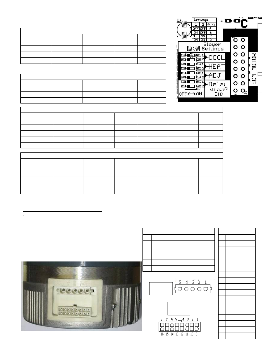
The operation of the motor requires two main connections: the power input connector which is 120VAC,
and the signal input connector from a 24VAC thermostat. Figure 1 shows the location of the connectors
on the motor. When wiring your ECM, the pin
locations are crucial in assuring that no damage is
done to the motor or the control. The figures show
the pin locations for both connectors, when viewing
the motor as shown below
ECM REH/REL 750 Heating Speed Selection
Burner
Firing Rate
Heat Switch
#1 Position
Heat Switch
#2 Position
Program Heating
Air Flow
0.60 GPH
ON
ON
D
950 CFM
0.75 GPH
OFF
OFF
A
1175 CFM
0.85 GPH
ON
OFF
B
1325 CFM
ECM REH/REL 1000 Heating Speed Selection
Burner
Firing Rate
Heat Switch
#1 Position
Heat Switch
#2 Position
Program Heating
Air Flow
1.00 GPH
ON
ON
D
1575 CFM
1.25 GPH
OFF
OFF
A
1925 CFM
ECM REH/REL 750 Cooling Speed Selection
AC
Tons
Cool Switch
#1 Position
Cool Switch
#2 Position
Program Cooling
Air FlowY2
Cooling
Air FlowY1
Air Flow
“G”
4 Tons
OFF
OFF
A
1600 CFM
1200
800
3 Tons
ON
OFF
B
1200 CFM
900
600
2-1/2 Tons
OFF
ON
C
1000 CFM
750
550
2 Tons
ON
ON
D
800 CFM
600
550
ECM REH/REL 1000 Cooling Speed Selection
AC
Tons
Cool Switch
#1 Position
Cool Switch
#2 Position
Program Cooling
Air Flow Y2
Cooling
Air FlowY1
Air Flow
“G”
5 Tons
OFF
OFF
A
2000 CFM
1500
1000
4 Tons
ON
OFF
B
1600 CFM
1200
800
3 Tons
OFF
ON
C
1200 CFM
900
600
2-1/2 Tons
ON
ON
D
1000 CFM
750
550
Signal Connector
Pin Description
1 C1
2 W/W1
3 C2
4 DELAY
5 COOL
6 Y1
7 ADJUST
8 OUT-
9 O
10 BK/PWM
11 HEAT
12 R
13 EM/W2
14 Y/Y2
15 G
16 OUT+
Power Connector
Pin Description
1
JUMPER PIN 1 TO PIN 2
2
120 VAC LINE INPUT
3 CHASSIS
GROUND
4 AC
LINE
5 AC
LINE
Signal
connector
Power
connector