Function description hardware – BECKHOFF M1110 User Manual
Page 3
M1110 Parallel Input / Output Box
Beckhoff II/O-System
Date 09.03.93
Version 2.1
Page 3 of 17
1. Function Description Hardware
M1110
About the Hardware
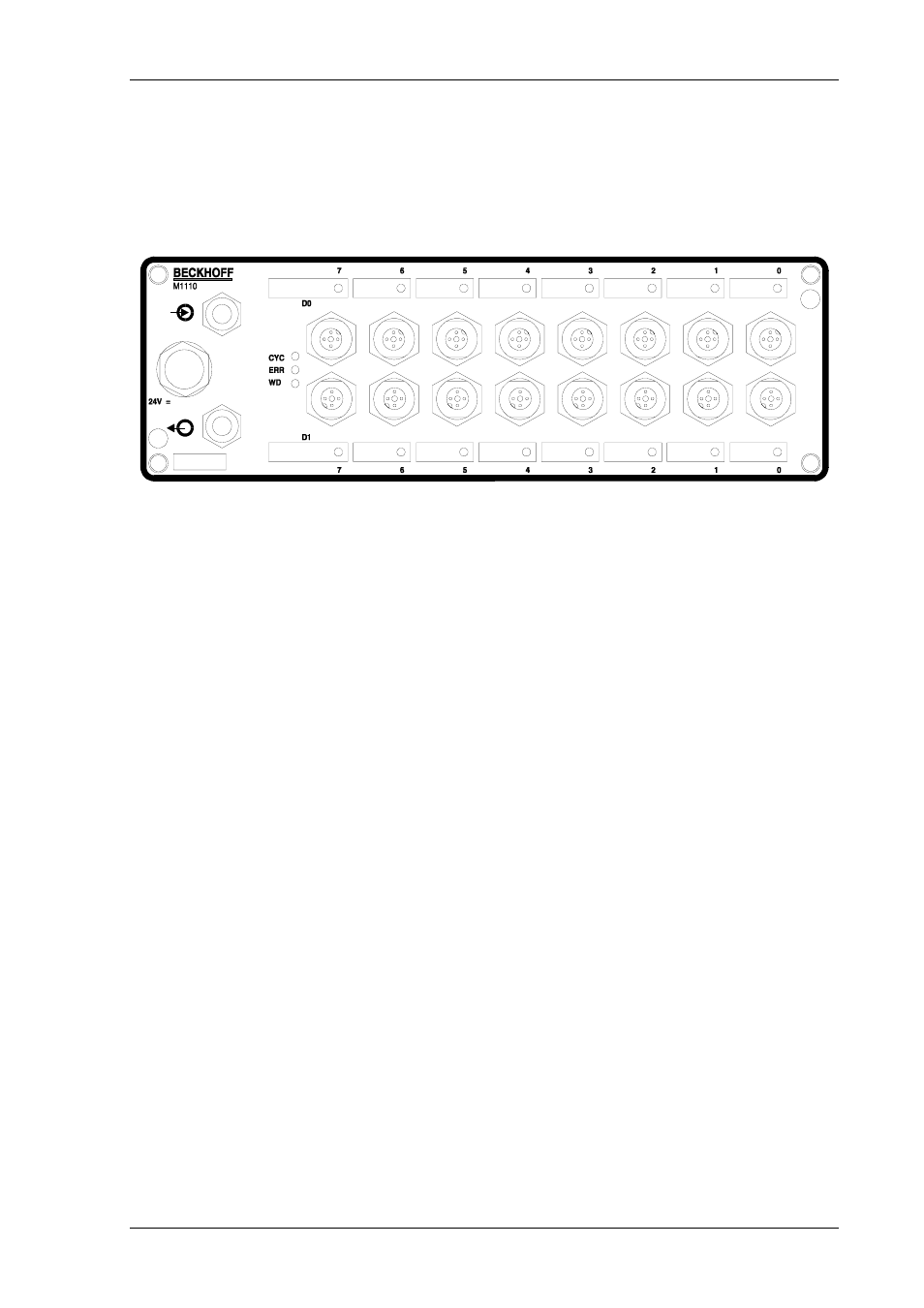
The parallel module M1110 is an input / output module used in the II/O system. There are 16
Standard 24 V inputs / outputs, which achieve 2 ports of 8 bit each.
These 2 ports ( D0,D1 ) correspond to the Data bytes in the FO transmissions protocol and
according to the way they are used, they can be configured as input or output.
Each input / output has a LED, that indicates the current state. In addition there are three
diagnosis LEDs for the II/O fibre optic ring:
LD1
The green ’CYCLE’ LED is switched on by each start bit of a telegram and is switched off
again by the stop bit.
LD2
The red ’ERROR’ LED is switched on after recognising a bad telegram (checksum, frame).
After a sequence of three correct telegrams (checksum, frame) were processed it is switched off
again.
LD3
The green LED ’WATCHDOG’ is switched on by a valid writing telegram with matching
address. If in a 100 ms afterwards no further telegram, which has the properties defined above, is
recognised a special unit of the module switches off all outputs.
The cartridge is according to IP65 protection norm designed as a compact, splash-proof and
dust proof box.